Yep, I don't live by the seaside.
I live about 12 miles from the ocean in an area that is known for its heat, humidity and salty air (Fort Lauderdale Florida). I have home made PC boards that I made back in the 70's. None have been protected and all are still alive.
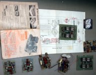
The picture shows a few Plastic Tigers and Universal Tigers I made in the late 70's. The two complete ones spent a few years in the sound system in my 70's van.
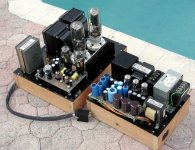
Here are two pictures of the first two Tubelab amp prototypes. They still have their home made PC boards and are both over 7 years old. Both still work. The 845SE operates on 1100 volts and the power supply is all PC board based. Note the swimming pool in the background.
Attachments
Here's the preliminary schematic of what I want to try. The outputs tubes are direct coupled, so I don't expect blocking distortion, though there will be gentle clipping if the grids on the outputs go positive. All the stuff inside the dotted lines is going ( has gone, as the layout is done) on to one fairly small PCB, so the insides of the amp will not be as cluttered as before. The pots will be used to tweak the overall bias on the output tubes. I took advantage of the direct coupling to put in place a "garter" bias circuit to help balance the output tubes, hoping to get rid of an extra couple of pots that way. Since the input stage runs on low voltage. I can bias it up with some bench supplies and check it out before I mate it with the rest of the amp.
If you substitute tubes for the jfets in the input stage (6EW6s or some hi-mu VHF triodes, I'm not sure which) , it's the topology I'm considering for the driver card on my ST70 not-clone (just the output XFMRS and the chassis will be like the original).
If you substitute tubes for the jfets in the input stage (6EW6s or some hi-mu VHF triodes, I'm not sure which) , it's the topology I'm considering for the driver card on my ST70 not-clone (just the output XFMRS and the chassis will be like the original).
Attachments
Ok, how does it work? The circuit utilizes a differential jfet input with folded cascode loading. The input diff pair is Q6 and Q7. The 2SK117 is a part with about 1/2 the transconductance of the 2SK170 and much lower input capacitance, still with respectable noise performance. The differential pair tail is fed by current source Q8, a Supertex depletion mosfet. Q8 is also the "boss current" source, setting the levels for the rest of the circuit. Tail current for the diff pair is set at 6ma, meaning that Q6 and Q7 will be each pulling 3mA. Current source Q8 also feeds a current mirror (Q9 and 10), which in turn feeds the top current source loads (Q1-Q3). Q1-Q3 form a current mirror that provides current source loading for Q6 and Q7. The ratios between resistors R2, R5/R27, and R3 are set such that Q1 and Q3 each drive 4ma into the drains of Q6 and Q7. The excess current (1mA) feeds cascode transistors Q4 and Q5, and is used to establish the bias levels of the output tubes. Pot R27 is used for fine setting of the output bias.
The attached circuit is the fancy-pants implementation, and uses a fair number of parts. An extreme stripped-down version would keep the Q8 diff pair tail current source, lose Q9, Q10, and Q1-Q3. The drain load for Q6 and Q7 would be replaced with a pair of 1.54k resistors. This would work ok, as long as a stiff voltage (D11 in this case) is used to clamp the bias on the folded cascode transistors. It would be interesting to see if there is any perceived difference in performance between the two approaches.
The attached circuit is the fancy-pants implementation, and uses a fair number of parts. An extreme stripped-down version would keep the Q8 diff pair tail current source, lose Q9, Q10, and Q1-Q3. The drain load for Q6 and Q7 would be replaced with a pair of 1.54k resistors. This would work ok, as long as a stiff voltage (D11 in this case) is used to clamp the bias on the folded cascode transistors. It would be interesting to see if there is any perceived difference in performance between the two approaches.
Good spot, the 39V zener in the bottom should be the other way ( It's shown correctly in the layout, which was done free-hand and was not coupled to this schematic). It's true that I could use a p-channel input stage for a simpler approach, but the folded cascode separates the bias current in the input stage vs the current in the gain resistors and allows one to optimize for more loop gain. I may try the p-channel approach on another amp. Having said that, appropriate n-channel input devices are more available.
Regarding P-channels, if you want to ignore the 2SJ74 as unobtainium ( I have some, but I don't know where I'd get more), this leaves devices like the 2N5460-62 (low gain) or short channel devices like the J175-J177, or small signal mosfets from Supertex and Zetex/Diodes, Inc. I'll fix up the current schematic and gin up one of the p-channel approach when I get some time.
Regarding P-channels, if you want to ignore the 2SJ74 as unobtainium ( I have some, but I don't know where I'd get more), this leaves devices like the 2N5460-62 (low gain) or short channel devices like the J175-J177, or small signal mosfets from Supertex and Zetex/Diodes, Inc. I'll fix up the current schematic and gin up one of the p-channel approach when I get some time.
The short channel is more like a crappier pentode. The long channel is like a good pentode. One thing I omitted to mention is that wringing out the folded cascode stage for the Lil' Devil is a preliminary to adapting it to tube inputs for my "ST-70" amp, where no vacuum-state p-channel devices are available. For input tubes, I'm limiting myself to 7 pin devices (less space, which is critical, as I'm using 4 envelopes intead of two). I'm wavering between a pentode like the 6EW6 or a triode like the 6HA5.
P tube emulation:
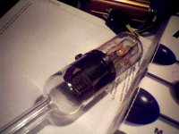
and a real P tube(ion gauge tube):
I recently found that there are actually sealed ion gauge tubes available for calibrating an ion gauge controller. Around $150 each though, and only good for microamps I think. Just a gassy radio tube should work though if the typical voltages are inverted.
and a real P tube(ion gauge tube):
I recently found that there are actually sealed ion gauge tubes available for calibrating an ion gauge controller. Around $150 each though, and only good for microamps I think. Just a gassy radio tube should work though if the typical voltages are inverted.
Attachments
Last edited:
Ok, next time I'm down in the basement I'll check and let you know. I snap this stuff up whenever I find it at a reasonable price, whether on Ebay or at local surplus stores. I also use a skinnier teflon coax that's translucent beige in color, whatever I get my hands on first in the chaos that is my basement. Both seem to work equally well for audio purposes.
Correction to the above N-JFET driver scheme:
The JFET drains are current source like, so will not be affected by the voltage variation on a top CCS tail as shown. Hence no useful differential effect. So the alternate scheme, with a CCS tail (to -50V say) on points Z and Z' is required to get differential action. (points X and Y can just go to some positive +15V or so, maybe thru some degen. resistors to linearize [not shown].)
For a local Schade type feedback setup, from the output tube plates, the ends of R5 and R6 could be connected to the plates (using high Ohms) instead of the Q3 and Q5 (arrgh, should have been Q4) drains shown. The inverting JFET input can then still be used for global feedback.
Could probably leave in a DC only LF feedback connection from the grid drive outputs back to the JFET sources for bias stability. (not shown)
See new diagram:
Attachments

Last edited:
The DC only LF feedbacks, for output tube bias stability, could even come from current sense resistors placed under the output tube cathodes (which could be Cap bypassed, and act just like a normal autobias setup as well, at least for class A). Hmmm, for class B maybe just put a big cap between the cathodes to shunt out the class B peaks.
Last edited:
As soon I ditched my previous input scheme for a DC coupled one, I incorporated the Blumlein "garter" feedback scheme to equalize the bias current between the output tubes. As you pointed out, it's an easy addition. Back when I started this project, I didn't know about the Blumlein bias circuit - now I try to incorporate it as a matter of course if it doesn't gum up rest of the design too much. I'm starting out with feeding back ~2V worth of the total bias current for autocorrection. This is about 9% of the planned total bias voltage of -22V. This may change, depending on how the output tubes actually behave.
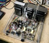
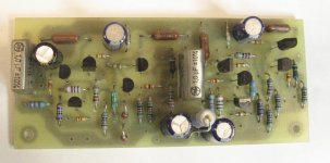
Attached is a picture of the front end board all stuffed and ready to go. It utilizes a simplified version of the folded cascode scheme presented a few posts ago, so I can optimze both the bias current in the input stage and the current in the load resistors that actually drive the output grids (and keeping the required negative bias supply to a reasonable level). Biasing up the board by itself with bench supplies at +20V and -50V, things read out ok, and the input stages balance pretty well, as the input jfets were matched to within a few millivolts. The card you see has the input circuitry for both channels, and measures 1.875" by 4.5". This will considerably releive the congestion inside the chassis, as there will only be one card inside the box instead of two. Next step will be to rework the chassis and power it up with bench supplies. Schematics will folow later. I need to find out if I have sufficient feedback from the output stage to reasonably center the output bias over a number of tubes.
Attached is a picture of the front end board all stuffed and ready to go. It utilizes a simplified version of the folded cascode scheme presented a few posts ago, so I can optimze both the bias current in the input stage and the current in the load resistors that actually drive the output grids (and keeping the required negative bias supply to a reasonable level). Biasing up the board by itself with bench supplies at +20V and -50V, things read out ok, and the input stages balance pretty well, as the input jfets were matched to within a few millivolts. The card you see has the input circuitry for both channels, and measures 1.875" by 4.5". This will considerably releive the congestion inside the chassis, as there will only be one card inside the box instead of two. Next step will be to rework the chassis and power it up with bench supplies. Schematics will folow later. I need to find out if I have sufficient feedback from the output stage to reasonably center the output bias over a number of tubes.
Attachments
Here's the next circuit rev. Some resistor values might change, depending on what it will take to get the output tubes to balance. I haven't decided whether I'll use a zener string or a tap on the SMPS output transformer to bias the output tube screens. I'm also toying with the idea of connecting all the output tube in series and using a 25V output supply to power the filaments. This would also be used to run the positive rail of the input board. The concept sorta pricks at my "sense of rightness". Pros and cons?
Attachments
- Status
- This old topic is closed. If you want to reopen this topic, contact a moderator using the "Report Post" button.
- Home
- Amplifiers
- Tubes / Valves
- Lil' Devil P-P Amp