Greetings All,
Well I tried to build a Brook 12a clone using the schematic attached.
I've run into several problems and have run out of ideas. So I turn to this forum where I'm consistently amazed at the depth of knowledge. Help?
I had my transformers built by Heyboer and they did a nice job, however they threw me a curve when they added a center tap to the 2.5v filament supply.(2A3s)
If I ground the center tap I get music at a normal volume but about 150mv of hum. The 700ohm resister R17 get insanely hot and voltages are very low, 165vdc at pin 2 of the 5U4G instead of 340vdc.
If I don't ground the center tap the amp is quiet but so is the music, no volume and very tinny sounding. The voltages go much too high at 444vdc at pin 2 of the 5U4.
The only change I made to the construction was leaving out resistors R20,R21 and capacitor C6. (I did try adding these guys in to the circuit using the 2.5 center tap but it didn't make much difference.)
What am I missing? Is this one of those misguiding schematics like the Hafler-Keroes Ultralinear?
Anyhow I'm at the point where I'll listen to any suggestions short of scrapping the whole project.
Thanks in advance.
Brian
Attachments
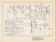
Something is not correct on that schematic, the cathodes (filaments) of the output tubes need to go to ground some how, usually a center tapped winding. Also what's funny are the voltage readings for pins1 & 4 of the output tubes. You have half the voltage on pin1 and the other half on pin4, that implies a center tap since all of the measurements in the chart are referenced to ground. The * note has the full voltage measured between pins 1 & 4. What are the voltages on pin3 of the 2A3s. Are all of your voltages OK otherwise?
Craig
Craig
Since the amp works more or less with the grounded C.T. let's assume it needs to be grounded. The voltage/resistance chart implies that anyway. Now why is your bias voltage so low? C3 in backwards? Also with the bias so low the outputs are running very very hot, therefore hot parts and low voltages are the result.
Craig
Craig
Still need help with this?
The parts you left out (R20,R21,C6) make a voltage divider to bias up the 6.3 VAC heaters.... You need add this or try the 6.3V ct to ground. That should help with the hum problem.
I agree that the polarity of C3 is incorrect on the schematic you posted
(The plus side should go to ground)
Yes, R17 will get hot... 67V/700R= 95ma (the total current the amp draws)
67V * 95ma = 6.4Watts (Hope you used a 25 or 50watt resistor here)
This 700R is how you get the -67V for the 2A3 grid)
I also agree that the 2.5VAC CT should go to ground.
For the 2A3, You should end up with about 330V at the plate, -67V on the grid and 0 V on the cathode.
Please provide an update.... I'm thinking of building one of these.
up and running
Greetings Sgerus,
I had set the project aside for a while until this fall. What I did change when I went back was I ran one side of the 6v filaments to ground.(floated?) Just like the schematic!
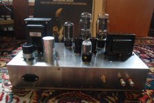
Amps are working now and sound pretty good. Here's a picture of the one of the completed amps.
Greetings Sgerus,
I had set the project aside for a while until this fall. What I did change when I went back was I ran one side of the 6v filaments to ground.(floated?) Just like the schematic!
Amps are working now and sound pretty good. Here's a picture of the one of the completed amps.
Attachments
Still need help with this?
The parts you left out (R20,R21,C6) make a voltage divider to bias up the 6.3 VAC heaters.... You need add this or try the 6.3V ct to ground. That should help with the hum problem.
I agree that the polarity of C3 is incorrect on the schematic you posted
(The plus side should go to ground)
Yes, R17 will get hot... 67V/700R= 95ma (the total current the amp draws)
67V * 95ma = 6.4Watts (Hope you used a 25 or 50watt resistor here)
This 700R is how you get the -67V for the 2A3 grid)
I also agree that the 2.5VAC CT should go to ground.
For the 2A3, You should end up with about 330V at the plate, -67V on the grid and 0 V on the cathode.
Please provide an update.... I'm thinking of building one of these.
Hmm i though that 2a3 specs were 250v plate typical, and 300v absolute maximum. 330v isnt a bit much?
Sadly, this Sams schematic (Post #1) seems to be the only one available. All the rest on the internet appear to be copied from Sound Practices which is a copy of the Sams with Joe's commentary about the 10C and a request for the Klipsh 12A schematic.
Anyway, the mistake in the schematic appears to be with the grounding scheme and there appears to be two ways to fix it. We can only guess at the correct way since we don't have an original Brook schematic.
The problem, obviously, is that there is not correct biasing for the output tubes. Here's my best guess as to the correct grounding scheme:
Connect R17 between chassis ground and the center tap of the 2A3 filament transformer. Connect C3 across R17 with the negative end to ground. Connect the center tap of the power transformer secondary to ground. Connect R16 to ground. That should work fine but I don't think that is the way Brook designed it.
I think that the original intent was for R17 to be in series with the chassis ground (that is between the ct of the power transformer and virtual ground). All the grounds would be connected to the positive end of R17 which becomes a "virtual" ground. The 2A3 grid resistors (R16) would be connected to the secondary center tap. This would provide the bias for the 2A3s. See the Peerless A100A for an example of this bias scheme.
Last edited:
Kevin,
Do you know any of the parameters of the 12A plate choke other than 3600 DCR? I've never had any luck chasing that information down.
Thanks,
Unfortunately I don't have any information on this choke either, and it has been at least 5 yrs since I last worked on one..
The problem, obviously, is that there is not correct biasing for the output tubes.
If I understand this circuit correctly, you don't need a resistor on the 2A3 cathode because the grid (of the 2A3) is at -67 volts and the cathode/heater is grounded (0V)
So Briney,
(or anyone else that has listened to a Brook 12A)
Have you had any tube amps before building this one? If so, How do like the sound of this compared to the others?
Also, what are the values of C2 (the 3 in 1 power supply cap)
-Thanks
Dynaco ST70 at least it started out that way, 300b set based on a JEL design, Hafler-Keroes Ultralinear. The Brook is a nice sounding amp. I don't think it colors the music too much.
I'm enjoying listening to them through my Klipschorns.
The 3 way is 30X30X30.
Kevin,
Do you know any of the parameters of the 12A plate choke other than 3600 DCR? I've never had any luck chasing that information down.
Thanks,
When I ordered from Heyboer I described it as a 3 lead choke with center tap. 3,600 ohms overall. Must be able to handle 10ma per half. It's been about a year since I ordered and I'm referring to my notes from the time. If you want to order from them the part number is HTS-10087.
- Status
- This old topic is closed. If you want to reopen this topic, contact a moderator using the "Report Post" button.
- Home
- Amplifiers
- Tubes / Valves
- Brook 12a clone