Hello all, I'm a relative "newbie" from Australia.
I've been building amps for a few years now - mostly 2 x EL84 in push-pull for 15W guitar amps for myself and a couple of mates. I've come up with a great formula over that time, using 1 x ECC83S (12AX7) and 1 x ECC82 (12AU7) in the pre-amp with a TMB tone-stack. I included Master Volume and Gain controls to provide a bit of extra versatility. I've settled on a bridge rectifier based power supply for the sound I was chasing. I'm pretty happy with the 2 x EL84 power supply I've developed (check out the attachment) - but confused when it comes to adapting something similar to a 4 x EL84 amp. Do I just beef up the VA on the power transformer secondary to 87 (280V @ 310mA? That is, add an extra 65mA each (max) for the 2 extra EL84's or would I also need to beef up the the first stage RC network. If so - any ideas? I'm just trying to make the new version as reliable as the old one. If you'd like to see the 15W power amp or my proposed 30W power amp, I can post those as well.
Sorry to rave on, but any help would be appreciated.
Attachments
Hi Eric,
I presume when you say 4 x EL84 you are planning to operate in parallel push-pull (PPP). Roughly speaking, the power supply will need to deliver twice the current, so indeed your transformer should be able to handle twice the load, but the voltage drop across your resistors in the CRC network will also be twice as much. The best way to think about the design is that you want two power supplies in parallel to give the same performance as what you have now driving two tubes. This would mean double the capacitance and half the resistance in the CRC network.
In truth, this may be neither practical nor necessary. Try out PSUD to compare the ripple and voltage sag under load for different configurations.
Note also that your output transformer will need to have half the input impedance to have similar performance to your current design.
-Eric
If the tubes are running class A you probably won't have to upgrade the driver stage. But if you are running AB or B, you will need a stronger driver. Otherwise the grid current will overload it.
When paralleling tubes it's wise to include parasitic suppressors in the grid and plate leads, say 100 Ohms for a wild guess.
When paralleling tubes it's wise to include parasitic suppressors in the grid and plate leads, say 100 Ohms for a wild guess.
4 x EL84's parallel push-pull power supply
Thanks for your help so far Torrence and Bob91343.
Yes, I forgot to mention that the 4 x EL84's would be in parallel push-pull. I've added 2 more attachments showing the current 2 x EL84 power amp and the 4 x EL84 power amp as it will probably be built. I can't go much further with the turret board until I settle on the power supply components.
What do you guys think?
Attachments
Last edited:
What do you guys think?
I think that the 10K resistors (1 watt) in your psu are too hot.
I think that the 10K resistors (1 watt) in your psu are too hot.
Actually, I didn't notice this before. Surely this is a typo. A current of 50 mA across 10k would drop 500V...
Actually, I didn't notice this before. Surely this is a typo. A current of 50 mA across 10k would drop 500V...
Well - with reference to the first attachment (EDLSUP15.pdf) - point A measures 360V @ 50mA, point B is 263V @ 8.4mA, point C is 231V @ 3.5mA and point D is 217V @ 1.2mA. It's no typo - in practice, I installed all 10K 2W resistors. The amp works extremely well. Please check the attachment.
For the 30W (4 x EL84) version, after torrence's coments, I was thinking of putting an extra 47uF Electrolytic before point A and changing the A-B resistor to 470R 5W as well as increasing the last 2 Electrolytics (C&D) to 15uF. Do you feel it necessary to increase the second (point B) 47uF Electrolytic as well? I guess the new board will be about 25% longer to accommodate the extra components.
Thanks again for the tips guys!
Attachments
The amp works extremely well. Please check the attachment.
Eric, what does the amp sound like? Vox AC30 type? What kind of music are you playing?
..Todd
Eric, what does the amp sound like? Vox AC30 type? What kind of music are you playing?
Hello Todd,
The 15W I made is really a cross between and Fender (pre-amp) and an AC15 (power amp). The tone-stack is essentially Marshall and I've given it a Matchless Lightning style MV with a 1M Lin pot straight across the output of the last stage of the preamp. Not ideal, but it serves the purpose. With the MV on full, using the original Volume control as it was intended, it's a nicely clean Amp - even useful for Electric-Acoustic work. However, using the Volume pot as the Gain, slowly reversing the situation will dirty it up a little for blues and to the extreme, crunch up quite nicely for a few Jet numbers. The MV doesn't take the "edge" from the pre-amp even at lower volumes. It also takes extremely well to pedals - if need be.
Being born in the early 60's, I'm still into anything from Wings to Bowie, to Dragon, to Creedence, to Eagles, to Led Zeppelin, to Foo Fighters, to Jet, to BTO, to Shadows, to Presley, to Deep Purple . . . and the list goes on. There's an amazing number of artists these days venturing back to their "roots". Great for us old guys.
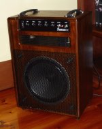
The Amp mikes up well through a PA for small gigs or studio work, but I'd really like to do a 30W version to see if it can stand up on its' own. Some say the magic may be lost with PPP - I guess I'll find out the hard way. I've included a shot of the finished 15W Amp - apologies in advance for the quality of the photo.
Attachments
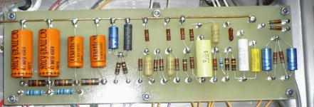
Nice soldering work there Eric. Very neat. I need to take this approach.
Thanks Brit01,
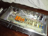
I've been a sparkie (Electrician) for about 33 years, the last couple of decades in technical fields. That helps with the soldering. I probably went a bit overboard on some of the turrets though - some had to be wire-wrapped to accomodate the component leads and as such needed a bit extra solder. The trick is not ot overheat the join, but still get good run-through for an effective bond.
I've added another shot if you're interested. If you were wondering, the small circuit board mounted on the PT bolts has a small bridge rectifier, resisitor and electro for the LED on the front panel - cheers.
Attachments
- Status
- This old topic is closed. If you want to reopen this topic, contact a moderator using the "Report Post" button.
- Home
- Amplifiers
- Tubes / Valves
- 4 x EL84 (6BQ5) in Push-Pull - Power Supply