Folks,
I've been enjoying some amplifier design for the past couple of days. I started out with a bunch of Pinnacle 6J5 triodes and a JJ 300B. The OPT is an Edcor CXSE25-8-5k, which supposedly should have a 5 kOhm primary impedance. It actually measures 4.2 kOhm. I don't know if this is due to production tolerances or a mistake by Edcor. I don't really mind as this allows me to get a tad more power out of my 300B.
I have tried a couple of different topologies. Of course, the "standard" common cathode, cap coupled directly to the 300B. It sounded decent, but also sounded like it was out of breath at full volume. This was evident when watching the output on an o'scope as the output waveform would essentially be constant for a good 2 ms following a sharp transient. George (tubelab) describes this as "farting out" - he has an excellent write-up on the topic here. I was able to replicate this phenomenon in PSpice.
Adding a source follower, thus, arriving at the Tubelab SE circuit made a *HUGE* improvement. The amp behavior at/near clipping was greatly improved with no farting out visible on the scope (confirmed in PSpice sim also).
Even though I'm using LEDs and SS CSS'es (IXCP10M45) for bias I would prefer to avoid sand in the direct signal path. So I was looking for an alternative to the source follower. Joe Curcio pointed me to the anode follower. That works really, really well.
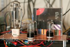
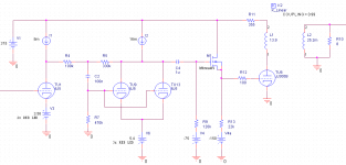
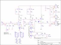
Attached is the schematic and prototype picture. I haven't decided if the source follower is needed or not. I keep going back and forth. The jury is still out. But it's pretty easy to swap the source follower in and out. Just let the 22 kOhm resistor float and short gate to source.
The gain of the first stage is about 20 V/V. The second stage (anode follower) is about 3 V/V. This allows me to drive the 300B to about 6.8 W at 3.6 % THD (just before clipping) with a 1 V(RMS), 1 kHz input. Adding the source follower lowers the THD at max power to 3 %.
The bias point for the 300B is 350 V on the plate, 60 mA bias current.
Do you have any suggestions for improvements to this circuit?
~Tom
I've been enjoying some amplifier design for the past couple of days. I started out with a bunch of Pinnacle 6J5 triodes and a JJ 300B. The OPT is an Edcor CXSE25-8-5k, which supposedly should have a 5 kOhm primary impedance. It actually measures 4.2 kOhm. I don't know if this is due to production tolerances or a mistake by Edcor. I don't really mind as this allows me to get a tad more power out of my 300B.
I have tried a couple of different topologies. Of course, the "standard" common cathode, cap coupled directly to the 300B. It sounded decent, but also sounded like it was out of breath at full volume. This was evident when watching the output on an o'scope as the output waveform would essentially be constant for a good 2 ms following a sharp transient. George (tubelab) describes this as "farting out" - he has an excellent write-up on the topic here. I was able to replicate this phenomenon in PSpice.
Adding a source follower, thus, arriving at the Tubelab SE circuit made a *HUGE* improvement. The amp behavior at/near clipping was greatly improved with no farting out visible on the scope (confirmed in PSpice sim also).
Even though I'm using LEDs and SS CSS'es (IXCP10M45) for bias I would prefer to avoid sand in the direct signal path. So I was looking for an alternative to the source follower. Joe Curcio pointed me to the anode follower. That works really, really well.
Attached is the schematic and prototype picture. I haven't decided if the source follower is needed or not. I keep going back and forth. The jury is still out. But it's pretty easy to swap the source follower in and out. Just let the 22 kOhm resistor float and short gate to source.
The gain of the first stage is about 20 V/V. The second stage (anode follower) is about 3 V/V. This allows me to drive the 300B to about 6.8 W at 3.6 % THD (just before clipping) with a 1 V(RMS), 1 kHz input. Adding the source follower lowers the THD at max power to 3 %.
The bias point for the 300B is 350 V on the plate, 60 mA bias current.
Do you have any suggestions for improvements to this circuit?
~Tom
Attachments
RFC = Request For Comments...
The verdict is in. The source follower stays. I'm using a 2SK3564 by the way. 2SK2700 or 2SK3566 would work also. Any MOSFET that can handle the voltage and has low input capacitance would be a good candidate here.
The source follower really cleans up the bass - especially at higher output power levels. The mids and highs remain largely unchanged.
By the way, the difference between the "normal way of doing it" - i.e. driving the 300B with a grounded cathode stage - and the "Tubelab SE" circuit is like night and day. I lost track of how many veils were lifted") . It's awesome. The difference in sound quality between the "Tubelab SE" and my circuit above is minimal - at least to my ears. It's mostly a way for me to get half-decent gain out of the stack of 6J5's I have in my box o' tubes. I like to have full power out with 1-2 V RMS in.
. It's awesome. The difference in sound quality between the "Tubelab SE" and my circuit above is minimal - at least to my ears. It's mostly a way for me to get half-decent gain out of the stack of 6J5's I have in my box o' tubes. I like to have full power out with 1-2 V RMS in.
I put "Tubelab SE" in quotes as I've made a few minor changes compared to the Tubelab SE. The biggest change is the LED bias. I might try resistor bias, but with the low dynamic impedance of LEDs I'm not sure resistor bias will do much to better the sound.
Also - using DC for the filaments on the 6J5's really cleans up things. Granted, I hadn't done anything to cancel the hum as I was planning to use DC all along. I just suddenly realized that I could supply the heaters from one of my lab supplies, gave it a whirl, and was quite surprised it made that much of a difference.
Now I just need to build a second channel. Or three more channels if I go for biamping.
~Tom
The verdict is in. The source follower stays. I'm using a 2SK3564 by the way. 2SK2700 or 2SK3566 would work also. Any MOSFET that can handle the voltage and has low input capacitance would be a good candidate here.
The source follower really cleans up the bass - especially at higher output power levels. The mids and highs remain largely unchanged.
By the way, the difference between the "normal way of doing it" - i.e. driving the 300B with a grounded cathode stage - and the "Tubelab SE" circuit is like night and day. I lost track of how many veils were lifted
. It's awesome. The difference in sound quality between the "Tubelab SE" and my circuit above is minimal - at least to my ears. It's mostly a way for me to get half-decent gain out of the stack of 6J5's I have in my box o' tubes. I like to have full power out with 1-2 V RMS in.I put "Tubelab SE" in quotes as I've made a few minor changes compared to the Tubelab SE. The biggest change is the LED bias. I might try resistor bias, but with the low dynamic impedance of LEDs I'm not sure resistor bias will do much to better the sound.
Also - using DC for the filaments on the 6J5's really cleans up things. Granted, I hadn't done anything to cancel the hum as I was planning to use DC all along. I just suddenly realized that I could supply the heaters from one of my lab supplies, gave it a whirl, and was quite surprised it made that much of a difference.
Now I just need to build a second channel. Or three more channels if I go for biamping.
~Tom
Last edited:
I usually bias my fets with 1M. Might lower distortion a tiny bit?
True. It would result in lower loading of the 2nd stage. That might explain the difference I'm seeing between the anode follower and anode follower + source follower.
Just out of curiosity, how much distortion do you get at 1W?
'bout a percent. See below.
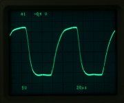
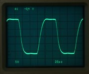
It turns out the major difference between the two topologies is in the transient response near full power. The two scope shots show the output voltage into an 8 Ohm load. The input signal is a 10 kHz square wave. Note that the -3 dB bandwidth of the amp is only just a tad more than 20 kHz so the 10 kHz signal is fairly bandwidth limited. I'll need to extend the BW somehow. But note how the anode follower clips softly on the tops of the waveform. This is because the anode follower runs out of gas when it tries to drive the 300B into A2. The source follower, on the other hand, drives a fairly nice square wave until the FET runs out of headroom (source voltage clips at -150 V).
I'll need to tweak the circuit. I think I can improve the THD of the first and second stage if I tweak the operating point a bit.
~Tom
Attachments
Last edited:
Tom,
Have you tried a CCS as the source load. Before I got my test equipment, I played around between resistive and ccs as the source load in my kt88PP. I liked the sound of the ccs better so it stayed. The decision was purely qualitative though. I would be curious to see if you can measure a difference?
Have you tried a CCS as the source load. Before I got my test equipment, I played around between resistive and ccs as the source load in my kt88PP. I liked the sound of the ccs better so it stayed. The decision was purely qualitative though. I would be curious to see if you can measure a difference?
Have you tried a CCS as the source load. Before I got my test equipment, I played around between resistive and ccs as the source load in my kt88PP. I liked the sound of the ccs better so it stayed. The decision was purely qualitative though.
I played with it in PSpice. I forget the results, honestly, but I think the CCS showed marginally better THD than the resistive load. I should give that a whirl in the real world and see how it performs.
I played around with the first two stages of the amp yesterday. The THD of the two stages is minimized when their plate voltages are equal. Makes sense... You don't want any DC current flowing in the feedback network. I'll try using three LEDs in the bias for the first stage to see if I can balance things out better.
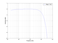
I also found one cause of the low bandwidth of the amp. The input cap of the two 6J5's in parallel along with the feedback resistance of 330 kOhm formed a pole at around 40~50 kHz. I changed the feedback network to 50k, 165k by adding 100k, 330k in parallel with the network already there. That increased the overall bandwidth of the two driver stages to almost 70 kHz.
It's yet to be determined how the changes in THD and bandwidth of the driver stages impact the overall amp once the 300B is inserted in its socket. Stay tuned.
~Tom
what is the current supplied from the - supplies?
The -75 gate bias draws no DC current. It can be formed by a voltage divider from the -150 V supply.
The -150 V supply supplies about 5 mA DC but should be capable of handling at least 10 mA as it provides higher current as the grid of the 300B is driven towards 0 V.
Ya know... I should probably update this thread. I have a better schematic which includes power supply and such. In addition, I went ahead and had PCBs made professionally. I have a good handful of spares if you're interested.
~Tom
It will be very nice if you update this thread. You know, my design is not ready. In the same time, nice to update also the thread with the national switchers: today other types are existing (with higher output voltage).
And thanks for the offer, but its not cheap to buy parts in the US.
And thanks for the offer, but its not cheap to buy parts in the US.
It will be very nice if you update this thread. You know, my design is not ready. In the same time, nice to update also the thread with the national switchers: today other types are existing (with higher output voltage).
And thanks for the offer, but its not cheap to buy parts in the US.
I ended up using LMZ12002 for the 300B filament supply and LM2734 for the 6J5 filaments. They work very well. I actually have boards with those parts mounted as I changed the design to be DC coupled, hence, the entire circuit changed. I won't be needing those boards...
The National switcher parts should be available world-wide. Farnell has them in Eurpoe... At Farnell prices, of course. In Denmark I used Aarhus Radio Lager (+45) 86246422 and Vejle RC Elektronik - (+45) 75832533. Scary... I haven't dealt with them in 10+ years and their phone numbers are still permanently etched into my brain.
Anyway. I'll update the thread...
~Tom
Final schematics
Folks,
This is where I ended up on this project. The design is done and tested. It performs well - both in the lab and in the living room. However, as I was about to wrap up this puppy, I decided to try DC coupling the driver stage to the 300B.
The power supply for one channel contains two Maida regulators - one for the positive B+ supply (385 V), the other for the bias supply, -185 V. The supply PCB contains two separate pairs of regulators to feed two separate channels of a stereo amp. Overkill? Perhaps... But you only live once. The regulators are designed to supply about 100 mA on B+ and about 30 mA on the bias supply. My original intent was to use an Antek AN-2T350, but that trafo is marginal for use with this supply -- especially when using tube regulators. The AS-4T360 might be a better choice -- or the AS-4T400, though, with the higher voltage trafos, it needs to be ensured that the electrolytics don't pop. I will leave that as an exercise for the reader... Thankfully, it's pretty easy to attach a cap external to the board. Also, by changing a couple of resistors, the board could be used to provide lower output voltages if need be.
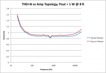
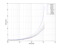
Anyway. The design is pretty solid and sounds good to my ears. At 10 W output power (into 8 ohm) the THD+N hits 2 % at 1 kHz. At 1 W out, it's more like 0.6 %. With the regulated supply, the amp has a pretty firm grip on the bass -- as firm as the Edcor OPT's will allow anyway.
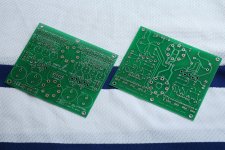
As you can see, I managed to get PCBs made before I switched gears and moved on to a different project. If anybody is interested in these, toss me a PM or email. I'll let you have them at my cost. I have four amp boards that have most of the surf mount parts mounted and five boards that are completely bare. I have four bare supply boards. Note that this is not intended to be a plug-'n'-play kit. It's boards and schematics. You connect the dots...
Enjoy.
~Tom
Folks,
This is where I ended up on this project. The design is done and tested. It performs well - both in the lab and in the living room. However, as I was about to wrap up this puppy, I decided to try DC coupling the driver stage to the 300B.
The power supply for one channel contains two Maida regulators - one for the positive B+ supply (385 V), the other for the bias supply, -185 V. The supply PCB contains two separate pairs of regulators to feed two separate channels of a stereo amp. Overkill? Perhaps... But you only live once.
The regulators are designed to supply about 100 mA on B+ and about 30 mA on the bias supply. My original intent was to use an Antek AN-2T350, but that trafo is marginal for use with this supply -- especially when using tube regulators. The AS-4T360 might be a better choice -- or the AS-4T400, though, with the higher voltage trafos, it needs to be ensured that the electrolytics don't pop. I will leave that as an exercise for the reader... Thankfully, it's pretty easy to attach a cap external to the board. Also, by changing a couple of resistors, the board could be used to provide lower output voltages if need be.Anyway. The design is pretty solid and sounds good to my ears. At 10 W output power (into 8 ohm) the THD+N hits 2 % at 1 kHz. At 1 W out, it's more like 0.6 %. With the regulated supply, the amp has a pretty firm grip on the bass -- as firm as the Edcor OPT's will allow anyway.
As you can see, I managed to get PCBs made before I switched gears and moved on to a different project. If anybody is interested in these, toss me a PM or email. I'll let you have them at my cost. I have four amp boards that have most of the surf mount parts mounted and five boards that are completely bare. I have four bare supply boards. Note that this is not intended to be a plug-'n'-play kit. It's boards and schematics. You connect the dots...
Enjoy.
~Tom
Attachments
-
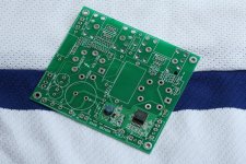 300B_AnodeFollower_Populated.jpg763.8 KB · Views: 1,144
 -
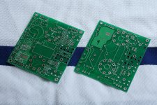 300B_AnodeFollower_PCBs.jpg763.5 KB · Views: 1,394
 -
 300B_Amp_2p0.png62.5 KB · Views: 1,547
 -
 300B_AnodeFollower_Supply_PCBs.jpg756.1 KB · Views: 1,087
 -
 Distn_vs_Power_385V_N185V.png32.9 KB · Views: 1,007
 -
 Ampl_vs_Freq_385V_N185V.png28.4 KB · Views: 293
 -
300B_Amp_2p0.pdf20.8 KB · Views: 420
-
300B_PSU.pdf19 KB · Views: 323
Last edited:
Pdissipated = (385-135)*0.012 = 3.0 W. So yes. A heatsink is required. Those would be HS1 and HS2 on the schematic. Aavid Thermalloy HS350.
As you can see on the PCBs, the two IXYS parts share the same heatsink. The total power dissipated in that heatsink is about 5.5 W. The MOSFET will need a heatsink as well.
~Tom
As you can see on the PCBs, the two IXYS parts share the same heatsink. The total power dissipated in that heatsink is about 5.5 W. The MOSFET will need a heatsink as well.
~Tom
I have two of the populated boards left and six blank ones. They're available for purchase on my website (see my signature).
I also have a couple of supply boards to go with them. The power supply is documented in the DeathTrap 500™ - An Engineer's Approach to the 300B SET thread.
~Tom
I also have a couple of supply boards to go with them. The power supply is documented in the DeathTrap 500™ - An Engineer's Approach to the 300B SET thread.
~Tom
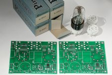
I found a stash of NOS Pinnacle 6J5GT and ceramic sockets that fit the boards. I'm making this amp available as a partial kit. I.e. two amp boards, four sockets, and four NOS 6J5GT tubes. This is enough for a stereo driver (obviously you'll still need to stuff the other parts on the board, add a power supply, 300B output tubes, and some output transformers).
~Tom
~Tom
Attachments
Last edited:
Actually, this circuit provides more gain than two sections of 6SN7 in parallel would. The gain of this circuit is high enough that you can use a CD player with a volume control to drive this amp. Full power is at around 1 V RMS. The first 6J5 provides about 20 V/V gain, the second, about 3 V/V for a combined total of about 60 V/V.
I used 6J5 as they (according to Morgan Jones) provide lower distortion than a 6SN7. Also, I have a stash of 6J5's... Why not use them.
~Tom
I used 6J5 as they (according to Morgan Jones) provide lower distortion than a 6SN7. Also, I have a stash of 6J5's... Why not use them.
~Tom
Last edited:
- Status
- This old topic is closed. If you want to reopen this topic, contact a moderator using the "Report Post" button.
- Home
- Amplifiers
- Tubes / Valves
- RFC: 300B driven by anode follower (6J5/6SN7)