Hi guys
I found some input transformer with separate secondary windings, good also for a phase splitter. Starting from my first idea, a friend made the following circuit for an OTL preamplifier.
I'm waiting for building the first prototipe and any previous comment is sincerly appreciate
thanks a lot
Filippo
www.audiofanatic.it
Attachments
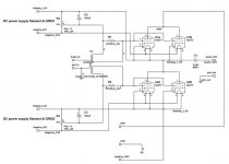
I called OTL only because the stage is like a tipical OTL amplifier, the HT is made with a dual PS, and the signal is taken at a virtual zero volt point between the two tubes. Anyway I put a condenser, because a little offset may occour, due to the tolerance of tubes.
The 100mF condenser is only a cap for avoid some residual hum because the fixed neg bias is taken directly from the heater supply and regulated with the pots.
Yes, is a weird scheme, I attach the first simplest idea when the basic circuit is better showed
... and sorry for my very maccheronic english
") )))))))))))
)))))))))))
ciao
Filippo
www.audiofanatic.it
The 100mF condenser is only a cap for avoid some residual hum because the fixed neg bias is taken directly from the heater supply and regulated with the pots.
Yes, is a weird scheme, I attach the first simplest idea when the basic circuit is better showed
... and sorry for my very maccheronic english
)))))))))))ciao
Filippo
www.audiofanatic.it
Attachments
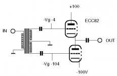
Actually it is not a white CF. It has absolutely no NFB, aside from that in the triodes themselves. They are fed in such a way as to negate the characteristics of a CF. For this reason, the circuit seen in the 3rd post in this thread is incorrect; the top tube is a cathode follower, while the lower is not.
It's just an elementary form of a SEPP circuit, thought the arragement of the schematic is a little confusing.
Tim
It's just an elementary form of a SEPP circuit, thought the arragement of the schematic is a little confusing.
Tim
- Status
- This old topic is closed. If you want to reopen this topic, contact a moderator using the "Report Post" button.
- Home
- Amplifiers
- Tubes / Valves
- OTL preamplifier