How would you label them on a guitar amp?
Two knobs, one labeled "smoke" and the other labeled "fire"!
I essentially have control over both DC levels and AC levels now, but knobs and current meters would be nice. G1 bias, G2 bias, and G2/G1 AC ratio controls would do it, as you can always vary the g2 drive by varying the input voltage.
I added a variable DC offset, which allows relative control of the DC bias between g2 and g1, and am now set up with +80V on g2, -22V on g1, 10mA idle plate current at 600V. The drive needed for output clipping is now 180V pk-pk on g2 and 44V pk-pk on g1. So now at signal peaks I have roughly +170 on g2 and 0V on g1, the same as pure screen drive would be. My plate swing only increased from 480V peak to 500V peak.
Allowing for 20V DC drop at peak signal current of 325 mA across the 60 ohm DCR of the OPT winding from CT to plate (I neglected before), and the B+ sag to 580V at full signal, I guess I'm getting down to about 60V a-k at peak signal, and a little over 70W out, which would be about right for the loadline after accounting for 5 or 6 watts AC loss through the OPT. I calculate 76W Po at the plates.
So it all seems to make sense after all, though now I'm scratching my head about the 90W number. With the losses I'm looking at through this OPT, it would take close to 650V B+ to get 90W out at 6K6 plate-plate.
I also found that 10mA idle current is about optimum to eliminate crossover distortion. 5mA was a little too low, and increasing to 20mA had no effect vs. 10mA.
At this point I'm wondering what real advantage there is to scaled drive over straight tetrode mode, at least with the 6DQ6. In my circuit, the increased effective plate resistance is a potential disadvantage, possibly requiring some global feedback (which might not be a bad idea anyway). Perhaps a tube like the EL509 or other >10 mA/V sweep tubes would be ideal for this use.
Next I think I'm going to try tetrode mode with the 6DQ6 to see how things compare.
I essentially have control over both DC levels and AC levels now, but knobs and current meters would be nice. G1 bias, G2 bias, and G2/G1 AC ratio controls would do it, as you can always vary the g2 drive by varying the input voltage.
...
Next I think I'm going to try tetrode mode with the 6DQ6 to see how things compare.
OK, separate AC and DC controls for each grid, so one can go from tetrode to g2-only drive or anywhere in between. so many ways to melt grids... or not!
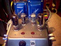
Baking pan ala g2/g1
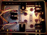
Well, I've got the sheet metal work done for a test jig. Baking pan ala g2/g1 drive mode.
Two OTs. One 100 W 4.2K P-P for starters (3.3K and 5K standing by), the other 25 W 8K is for an initial driver plate load. Heatsinks are for Mosfet grid drivers and a CCS driver tail. I'll probably change over to gyrators for driver loads eventually, like Michael's. The 2nd small OT will then be for the cathode CT choke for an elliptron mode later yet. Extra mountings already there for an anti-triode heatsink also. 6HJ5 finals for now. 6GF5 drivers for now. Optional 6LU8 drivers later or 9 pin 9DX base pentode + triode driver sockets in place also. So many variants to try out. I may have to build up a second test jig just to compare design changes.
Attachments
The danger with something that solid, is that one hooks it up to some speakers for a test and it never gets unhooked.
I have that problem with circuit boards and transformers on a piece of wood. My 6V6 Simple SE has been in that state for 2 years.
Two knobs, one labeled "smoke" and the other labeled "fire"!
"Smoke" goes from 0 to "Water", and and "Fire" goes from 0 to "Sky", for deeper purple reality!

I may build some finished amplifiers later using some real nice bake pans I found at K Mart lately. They have heavy duty aluminum and steel bake pans for around $13. And a shallow pan of same type which would work for a bottom. I'm thinking maybe space them apart 3/4 inch with spacers, put a clear strip around the gap and blue LEDs behind to light up the inside. That levitated blue glow look.
-----------------------------
"Two knobs...."
Need a bi- color LED atop each knob that changes from blue to red as you turn the knob. And some old fashioned flash bulbs that go off when the max setting is reached.
-----------------------------
"Two knobs...."
Need a bi- color LED atop each knob that changes from blue to red as you turn the knob. And some old fashioned flash bulbs that go off when the max setting is reached.
Last edited:
Back in the old days in Scouts, we used to camp out in an old two story barracks with bunk beds. There were ventilation gratings between the floors, some right above the lower bunks. One time we brought some of those huge flash bulbs with Edison bases on them. Then we removed a vent grating and lowered the bulb down on a lamp cord until it was just above a cohort in his bunk in the dark. Then we yelled "hey Bob", and plugged it in. Kaboom!! Good thing they had plastic coatings on them. Wasn't safe camping out there after that.
- Status
- This old topic is closed. If you want to reopen this topic, contact a moderator using the "Report Post" button.
- Home
- Amplifiers
- Tubes / Valves
- G1=G2/mu Scaled Drive Strawman Design