I was messin with a similar idea but run into two problems, not sure I have
chosen the most ideal ways for solving them...
Problem 1: Triode voltage amplification. Too darn linear, neither triode nor
screen have the right curves out at the bottom to cross without a glitch.
And also no guarantee this warms up before the Pentode it must control.
I've solved by using starved FET to round the bottoms into a nice crossing,
and solid scrape BJT for voltage amp scaled to both grids. The plate dipping
into the screen with no feedback to "fix" it, seems to round the top nicely.
Problem 2: This is a sim with imperfect models for grid and screen currents.
I really don't have a clue how well this correlates to reality, especially in
terms of what G1 with positive bias is likely to bleed... Or what affect the
positively bent shadow casts upon G2?
I've not made any progress toward solving this, other than make sure to
select a pentode without screen and grid alignment. I still worry the G1+
shadow focuses a hot spot directly onto G2? 6CA7, EL34, and GU50 all
seem likely suspects to not have any such alignments. There are not any
big space charge tetrodes with deliberate grid screen un-alignment???
Attachments
Late edit:
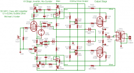
Q1 Q4 don't substitute well with 12ax7 (not enough current) nor 12at7
(not enough voltage gain). Mu isn't really needed where already Schaded
by grid divider. I might revisit this area to see if a small pentode might do.
Why the crossing glitch has not been looked into before? All the rest are
looking only at Class A or pure B? If I don't care AB crossing, I can make
the single ended behavior very much more linear.
Dump a constant current into G1, and drive G2 just like an Aleph pair...
Last edited:
Dump a constant current into G1, and drive G2 just like an Aleph pair...
Its plenty linear, but you won't get no soft limits nor a smooth AB crossing.
Here we forget to care what is screen drive voltage? Only care what is the
cathode voltage...
-----
Kentucky Sanded Chicken 5042F is original recipe below 900V and 6W.
Above those limits, extra crispie.
Attachments
Last edited:
re Ken:
In your schematic in post #41, the pentode Spice model must not be drawing any g1 current. R1 at 150 K will never hack it. Maybe connect g1 to Q1 emitter instead, except that will affect the input current gain -> faster turnoff or slower turn-on actually (positive g1 drawing current). Maybe just massage the divider resistors, as is, until you get the crossover curve needed. Hmm, no, this just affects the high current end of the pentode curve (g1 positive).
I've modded my curve tracer to include grid current curves now, so I will get some curves up by the end of the week hopefully. Some quick tests didn't show any particularly obvious g1 -> g2 focusing effect yet. I still have it all apart for mods to the stepper voltage power supply.
Last edited:
I question how well the SPICE models are going to work here.
I suspect that the tetrode model is unlikely to be of much help in evaluating the fine points of this mode of operation. It seems like they assume relatively high G2 voltage and have a simple diode model for +G1. Even if the focusing is not a problem, an accurate current model at low Vg2 and high Vg1 is required. G1 current will likely be over 100mA at peak. It's not clear if cathode resistance is modeled properly as the limit of emission is approached, which is also necessary to model this mode.
I have been looking into tube models and wonder if the Excem models are being used anywhere? They seem to have taken into account more of the edge effects, but still not sure about low Vg2 region.
Tube models 2
Since I don't have a stash of sweep tubes at hand, I've decided to go with transmitting tubes in my prototype. I think that means I'll try to build a good model for the 4CX250 type, but the actual construction may outpace the model development ;-). Of course I will do some in-circuit tracing. I think the only way to get he optimum idle point and seamless crossover will be through trial and error with the voltage ratio and idle current.
re Ken: Hmm, no, this just affects the high current end of the pentode curve (g1 positive).
Yes, the base follower corrects G1 with a strong feedback. G2 not so much...
Exact opposite your situation where G2 is corrected by the strong feedback.
I suspected 150K was a bit high, but without an updated model or real info,
just dividing in the dark.
In the second drawing: How many mA could a CCS safely dump into G1???
I hope that G2 in the Aleph variant will automagically pinch off and cloud up
extra electrons around G1, if G1 ever starts to become dangerously emissive.
In light of Q2 watchdog over runaway, do you think Zenier serves a purpose?
Last edited:
Here are my thoughts on the nature of the crossing glitch:
- Composite gm changes abruptly as one tube goes into cutoff. This can be mitigated by controlling the overlap and, in the case of scaled drive, the bias ratio of the 2 grids; i.e. if either g1 or g2 dominates the gm as cutoff is approached, then the gm slope will change
- Each side of the driver may see a slightly different copy of the output signal as feedback which may change abruptly in the crossover region. I think this causes the phenomenon discussed in another thread, where each side operates as an independent low impedance triode, leading to the behavior Schade discusses about triodes in class AB in his paper. One solution is a topology that combines feedback from both sides as in the coupling transformer in Schade's paper.
- The stored energy in the transformer leakage inductance causes back-emf as each side's tube cuts off. I have wondered if a minimum current through the tube e.g. 5mA would make any difference. Prevent the tube from cutting off completely. Is it then class A? ;-)
We got a few basic flavors here:
G2 follows drive signal, G1 at fixed voltage.
G2 follows drive signal, G1 at fixed current.
G2 follows drive signal, G1 scaled resistively.
G2 follows drive signal, G1 scaled actively.
G2 follows amplified voltage error sampled at cathode, G1 at fixed voltage.
G2 follows amplified voltage error sampled at cathode, G1 at fixed current. (Post #43)
G2 follows amplified voltage error sampled at cathode, G1 scaled resistively.
G2 follows amplified voltage error sampled at cathode, G1 scaled actively.
G2 follows amplified voltage error sampled at G1. G1 follows drive signal. (Post #41)
G2 follows amplified current error sampled at G1. G1 follows drive signal.
I wonder if there is any merit to:
G2 follows drive signal, G1 follows amplified voltage error sampled at G2?
G2 follows drive signal, G1 follows amplified current error sampled at G2?
(ie: actively varying G1 in attempt to maintain G2 at constant current?)
We need square law cutoff for smooth AB crossing without abusing global feedback
to merely hide the crossing problem. All the above probably too linear to for that...
Schottky diode or starved FET might fake the right curves with less problems than
GNF? Perhaps something akin to VischB for tubes?
Last edited:
I can't find any good modeling infos about G1 current when positive biased.
I'm thinking: Can I dumb this down to triode where the screen is my plate?
For purpose of figuring G1 current only...
Even if we ignore the true plate (or fudge some average on basis of screen
transparency) and get this down to just three terminals... What do I do now?
The only infos I can scrape up about how a triode's plate affects positive G1
current: relate to abusing plate as grid, and grid as plate, in "inverted triode"
1/Mu mode. Do you think this is still a relevant model for figuring grid current
when both plate and grid are positive?
Last edited:
SpringerLink - Journal Article
How to fudge realistic G1 currents into Duncan's tetrode model???
I should probably attempt a triode with known A2 grid curent first.
Just incase the link (from a search) turns to be invalid, or preview
some other page later... This was the preview page that I saw:
Ohyeah.. And EF86 model works OK for Q1 (posts #41 and #43).
One less sand to worry.
---
Hey, if I put CCS into G1, Volts outa be 1/Mu related to screen?
I mean, if the inverted triode model is truly applicable? Maybe we
don't need an external voltage divider at all?
Self inverted triode G1 drive? Iffen it works, think the parts saved!
Attachments
Last edited:

CCS might dumb g1 to DONUT or worse. But g2 is still active grid to the big plate.
Yet certainly not helpful preventing peak G2 voltage from approaching that plate.
I'm pretty certain we want G1 voltage to swing the same direction as the screen,
and this latest absurd idea of mine probably does exactly the opposite...
I cannot picture a scenario where CCS into g1 turns the whole pentode into a
DONUT. It just doesn't seem plausible that g2's effect could ever be completely
nulled by a mere constant current into the first grid.
In therory... No sim model for G1 as inverted triode. I ain't got time and space
to breadboard this as an experiment at home right now. And work would throw
a fit, though it would be a lot easier to plot on the bench with a GPIB power
supply and Labview. I need only low voltages for this test anyway. Probably
something I'd have to sneak in over a weekend. And not this weekend fo'sho...
Last edited:
Ken,
I think the usual estimates of grid currents are as some interception fraction of the passing current until other (plate or screen V vs g1 V) voltages drop down enough to give roughly parity attraction with the grid itself acting as a plate. In that vicinity the grid current begins a roughly square law increase from there on (until it burns up!). Spangenberg's book has some info on this I think. Just looking at the g2 current curves (versus plate V) on some tube datasheets gives a good idea. I would think the same kind of curve for pos. g1 current versus g2 voltage would apply. Apparently plate V must still be considered also (beside g2 V) for g1 current, since g1 current increases nonlinearly in the g2-g1/Mu setup while the two g2 and g1 voltages are both increasing by some ratio. Maybe have to consider the effective gm of each electrode times the voltage on that electrode and then compare with the similar product for g1 to determine the bounds of the square law ramp-up region(s).
The CCS on the grid setup (Donut) might make an interesting oscillator. Just use some high value resistor to B+ from g1. Plate (thru an Rload to B+) and g2 at some positive voltage. Then the increasing tube current ramping up will cause g1 to accumulate neg. charge by interception until it throttles the beam. The grid capacitance and pullup R forming an RC time constant network. If the grid -V overshoots the stable point, then R starts discharging the g1 charge faster than interception buildup and everything swings back the other way. Maybe overshoots the stable point again the other way , and then starts all over. Depends on whether it will overshoot the stable points, might require some L in the cathode to maintain current.
The idea(s) of using g2 say for error control are interesting. Reduced g2 voltage variation likely compared to g2 drive. Some years back a thread on effectiveness of UL operation got into the idea of an Op. Amp. to contol an active UL screen grid, so that plate voltage output would be linearized. Never got followed up on. Mainly was looking at what signal really was required on the screen in UL mode to get linear operation.
Also, some ideas relating Hawksford error correction (-unity error only feedback) to g1/g2 corrector control have come up before. All unexplored thus far.
Last edited:
I think the only way to get he optimum idle point and seamless crossover will be through trial and error with the voltage ratio and idle current
I have found that the triode models that I have downloaded (Duncans and others) vary from right on, to totally useless. This seems to depend on how well they were done, and how far you take them from "normal operation". A2 is verry iffy with any of them. In many models G1 draws no current even at +100 volts. The pentode models that I have used were even further off. A 6L6GC in normal pentode mode yields results that can be used to learn a few things. I have not gotten any useful results from any simulations involving screen drive or G1 = G2 drive. Perhaps we need better models. I still think that we are a long way from having models for vacuum tubes that are useful in non standard circuits. Real live circuit tweaking is still needed here. Maybe if it rains tomorrow.......
I think that means I'll try to build a good model for the 4CX250 type, but the actual construction may outpace the model development ;-). Of course I will do some in-circuit tracing.
A long long time ago in a world far away..... I got this idea to build the mother of all guitar amps using a pair of 4CX250B's. It really sucked as a guitar amp, but did a good job of eliminating all TV and radio reception within about a mile of my house. I trashed the amp, but saved the NIB 4CX250's the Eimac sockets, chimneys and the power transformers. I decided that it all would be better used for an RF amp, probably for 2 meters. Of course that was 20 years ago and it still hasn't been built. I know a lot more about tubes now than I did then, but the 4CX250 isn't high on my list to play with for audio. They are just too easy to blow up (so the ham linear guys tell me).
I see. Whoever dies with the most NOS tubes wins ;-).....Fanatics like George are a special case, as not everyone has a warehouse full.......
Well, contrary to popular opinion, I don't have that many NOS tubes, and the ones that I have have been purchased by me with some project, circuit, or experiment in mind. I did have a warehouse with over 100,000 unboxed, unsorted tubes in unknown condition. I have sold, trashed, or given away most of these since the rent to keep them is higher than they are worth. Of course I have kept anything that I could use for "science" and that includes anything that even looks like a sweep tube.
Since I don't have a stash of sweep tubes at hand, I've decided to go with transmitting tubes in my prototype.
I can fix that! Seriously if you are interested in experimenting with sweep tubes, and are willing to share your findings with the forum audience, and are not afraid of playing with odd filament voltages, I can send you a box full of sweep tubes. I can find multiple samples of useful tubes in odd filament voltages like 17DQ6, 25BQ6, 17AV5, 25CD6...... There are more experimenters here (including me) that could benefit from having useful models of sweep tubes than those willing or qualified to play with transmitting tubes like the 4CX250.
...models that I have used were even further off...Real live circuit tweaking is still needed here.
(...)
There are more experimenters here (including me) that could benefit from having useful models of sweep tubes than those willing or qualified to play with transmitting tubes like the 4CX250.
I could put the 4CX250 on the shelf for now and go ahead and get some 17 watt sweep tubes and a pair of OPTs for a 50 watt amp. (But Edcor takes eons and I already have the monster OPTs...)
Maybe I'll order the Edcors and start the project with my LS-55s.
As far as the tube model, no reason a model for a 17 watt sweep tube can't be adapted to the 4CX250 later... And the 50 watt amp is the one I would use everyday.
Cheers,
Michael
I could put the 4CX250 on the shelf for now and go ahead and get some 17 watt sweep tubes and a pair of OPTs for a 50 watt amp.
Send me an email or a PM.
A 50WPC amp using 17 watt sweep tubes sounds like a winner to me.
All I need are the quad of 6DQ6 (17DQ6 will work fine) and a pair 6K6 OPTs good for 60W or more. I have a 378CX that will do for the power transformer.
Also thinking about going with a 6V6 front end tube instead of the 6CL6...
Cheers,
Michael
All I need are the quad of 6DQ6 (17DQ6 will work fine) and a pair 6K6 OPTs good for 60W or more. I have a 378CX that will do for the power transformer.
Also thinking about going with a 6V6 front end tube instead of the 6CL6...
Cheers,
Michael
Attachments
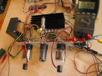
What's that smell?
I plugged in the sweep tubes, starting with 12DQ6s, to the scaled drive amp "tester" today and cranked up the B+. With the variac all the way clockwise to 600V of B+ (about 580 under load) I'm getting 67V Pk-Pk into 8 ohms, right at 70 watts Po, at clipping. The only thing getting hot is the load resistor.
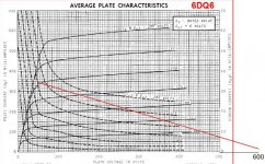
So far it's working out as planned, taking about 75V peak on G2 and 17V peak on G1 to reach the point on the G2 plate curve corresponding with 0V G1 and 150V G2. I don't know if G2 is doing 1/2 the work, but the voltage to do a given amount of work is 1/2 when G1 is also driven at G2/mu.
The idle current is 25mA on each side, with about +13V on G2 and -1V on G1 at 600V on the plate.
I'm now investigating a strange kink in the output that starts at about 15W Po (well above crossover) and moves up toward the crest of the sine wave as output is increased. Other than that, everything seems to be working out.
I also have a 600V tap on my ICT that will get me up to 750V B+, but I'm using 440VAC motorrun filter caps. I'll bet they will hold at least to 700V muahahaha
More scope shots to come, etc. as I proceed.
Cheers,
Michael
I plugged in the sweep tubes, starting with 12DQ6s, to the scaled drive amp "tester" today and cranked up the B+. With the variac all the way clockwise to 600V of B+ (about 580 under load) I'm getting 67V Pk-Pk into 8 ohms, right at 70 watts Po, at clipping. The only thing getting hot is the load resistor.
So far it's working out as planned, taking about 75V peak on G2 and 17V peak on G1 to reach the point on the G2 plate curve corresponding with 0V G1 and 150V G2. I don't know if G2 is doing 1/2 the work, but the voltage to do a given amount of work is 1/2 when G1 is also driven at G2/mu.
The idle current is 25mA on each side, with about +13V on G2 and -1V on G1 at 600V on the plate.
I'm now investigating a strange kink in the output that starts at about 15W Po (well above crossover) and moves up toward the crest of the sine wave as output is increased. Other than that, everything seems to be working out.
I also have a 600V tap on my ICT that will get me up to 750V B+, but I'm using 440VAC motorrun filter caps. I'll bet they will hold at least to 700V muahahaha
More scope shots to come, etc. as I proceed.
Cheers,
Michael
Attachments
Last edited:
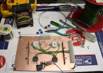
I guess that there is new life in this thread now! The clip lead and turret board furball that I tested in posts 29 and 30 has been stripped for parts. I performed a few experiments on it, and learned a few things, but it was too limited. I have played with Petes red board for several months, learning quite a lot, and discovering its limitations. Many screen drive experiments revealed high efficiency and power output, some tube melting limtations exist there too. As I mentioned in the red board thread, I need a new board, but I don't quite know what it is yet. So, I decided that a little prototype system that could be warped into an amplifier is what I need.
I thought about it for a while and this is what I came up with. It bears some resemblances to yours mechanically. The circuit is totally different. Mine is a cross between the red board and the circuit in post 29 with a mosfet replacing the triode.
Since I am trying to bring together several concepts that I have learned over the past 2 years, and test a few new theories, I call this the "grand unified theory amp".
Attachments
- Status
- This old topic is closed. If you want to reopen this topic, contact a moderator using the "Report Post" button.
- Home
- Amplifiers
- Tubes / Valves
- G1=G2/mu Scaled Drive Strawman Design