Hi Rick,
The Lundahl transformer just arrived yesterday, so I'll be drilling the chassis this weekend. I have all the parts gathered except the 0B2 tube. I will post picks as soon as it's done.
The 30/31 push-pull is still in the dream stages.
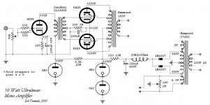
This one I came up with because I wanted a 10 watt tube amp to do a direct comparison with my 10 watt SS amp.
The Lundahl transformer just arrived yesterday, so I'll be drilling the chassis this weekend. I have all the parts gathered except the 0B2 tube. I will post picks as soon as it's done.
The 30/31 push-pull is still in the dream stages.
This one I came up with because I wanted a 10 watt tube amp to do a direct comparison with my 10 watt SS amp.
Joel,
For once (of late) I agree with you. I built it in 69-70 in original form. Later I scaled it to 50W. The heatsink was 2 foot square and needed forced air cooling! Parties could be heard at the end of the street. Police were called on occasions - but that was in my youth.
Back to the sound: Very similar to a reasonable P-P valve amp. beats any mediocre valve amp.
Cheers
AAAAH THE 6AQ5,  by all accounts a much under rated and neglected tube, with great potential one of joe, [forget his last name ]a frequent poster on audio assylum tubes forum, he reckons it will out perform any of the el-84's for sound quality , and cheap to find even in nos on ebay as it hasn't developed a "cult"following like some other tubes, from what I understand it can even be used to replace the 6bq5 in a circuit as it has many characteristics the same, there was a low power circuit from dynaco I had one time that could use either the 6bq5or 6aq5 without any major mods, good choice for a simple amp I LIKE THE circuit
 cheers, TC
by all accounts a much under rated and neglected tube, with great potential one of joe, [forget his last name ]a frequent poster on audio assylum tubes forum, he reckons it will out perform any of the el-84's for sound quality , and cheap to find even in nos on ebay as it hasn't developed a "cult"following like some other tubes, from what I understand it can even be used to replace the 6bq5 in a circuit as it has many characteristics the same, there was a low power circuit from dynaco I had one time that could use either the 6bq5or 6aq5 without any major mods, good choice for a simple amp I LIKE THE circuit cheers, TCJoel's back with a vengance...
Hi Joel,
Great design, interesting tubes and an individual take on topology. That's what we have been missing!
Constructive comments... let me see.... what would I try...
1) Snubbing the 1N4007s does clean up the reverse shutoff switch and might help the sound
2) split the 5.5k resisitor feeding the OB3 for a choke (156C say) cap into resistor might add to the dynamics a bit - but probably wouldn't as this seems to work better with pp.
3) Fixed battery bias???
4)try a 1uF capacitor between the OPT B+ feed and the cathode junction of the 6AQ5s - about all the gas regs would allow?
but I like it as it is. Nice, really nice.
ciao
James
OHHH, BTW, the guy I refered to in my earlier post was joe rosen, just about wrote a novel every time he posted, and very entertaining to boot, kinda miss his posts as I HAVEN'T SEEN ANY FROM HIM IN QUITE A WHILE, we corresponded once or twice but then when I was hospitolised for 2 months late last year we lost touch.... 
Phase Splitter
Hello ,
Are you sure that phase splitter transformer is not overkill ? I would have thought that with driving pentodes , a concertina phase splitter would have been adequate . A phase splitter transformer more costly than the output transformer ? Would there be any advantages ? With a concertina , loop feedback could also be implemented more effectively
Why use the gas regulators ? What do you think will happen to the supply rail when the amp is driven into class B ?
316a
Hi NickC,
I have found a significant improvement in my PP amps by adding this capacitor. IT improved all aspects of the sound, I was quite shocked by it. It is not a parafeed connection but is more akin to the Ultrapath connection. It's purpose is to provide a short high quality signal current return loop to the cathode. A typical value of about 40uF works best - I guess the exact value can be calculated by the incircuit output impedance of the stage and the required lf cutoff frequency. Haven't really thought that through yet. The 1uF is about the highest value the gas regulators will tolerate ... it's better than nothing
EC8010 said:
I hadn't looked at start up conditions - this looks like a problem. How serious would it be? Would delayed B+ solve it?
ciao James
is there much improvement in doing the cap from B+ to the cathodes of the output tube? parafeed right?
I have found a significant improvement in my PP amps by adding this capacitor. IT improved all aspects of the sound, I was quite shocked by it. It is not a parafeed connection but is more akin to the Ultrapath connection. It's purpose is to provide a short high quality signal current return loop to the cathode. A typical value of about 40uF works best - I guess the exact value can be calculated by the incircuit output impedance of the stage and the required lf cutoff frequency. Haven't really thought that through yet. The 1uF is about the highest value the gas regulators will tolerate ... it's better than nothing
EC8010 said:
At power-up, when the 6AQ5s are cold, those neon regulators will have to sink a lot of current. Are they up to it?
I hadn't looked at start up conditions - this looks like a problem. How serious would it be? Would delayed B+ solve it?
ciao James
How about replacing the output stage cathode resistor and cap with an *un*-bypassed SS constant current source set at 90-100mA? If the ccs is good eough it will force the output stage to be virtually perfectly balanced because the total cathode current will *always* be 100mA or whatever throughout the whole cycle. Even as the tubes age! It makes the output stage basically a long-tailed pair. Better hum rejection too. If one tube is a bit on the sad side, the drive to the good one is automatically reduced to compensate for it. You could then even earth one of the output tube control grids so that only the other one is driven so you wouldn't need a phase splitting transformer or any kind of phase splitting cct. It then needs double the drive voltage though.Joel said:Constructive comments are welcome.
With only one tube appearing to be driven (the "undriven" one is actually driven through it's cathode), instead of earthing it you could apply a small dc offset above or below earth to the undriven tube control grid to make the output stage have perfect dc balance too. The output tranny will love you for this.
It's something I always wanted to do but I don't have a suitable output transformer nowadays. D'oh!
CCS cathode bias
Been there , done that but the CCS will only force AC to be symetrical . In DC terms a pot between the cathodes would be required to optimise DC balance (and cancel any DC in the core) otherwise variable fixed grid bias will be required . I don't think this is possible with the IT transformer shown , unless it has separate secondary windings .
316a
- Status
- This old topic is closed. If you want to reopen this topic, contact a moderator using the "Report Post" button.
- Home
- Amplifiers
- Tubes / Valves
- A 10W ultralinear amplifier with unique features.