All the necessary info is hidden subliminally in my post. Look closely.Been there , done that but the CCS will only force AC to be symetrical . In DC terms a pot between the cathodes would be required to optimise DC balance (and cancel any DC in the core) otherwise variable fixed grid bias will be required . I don't think this is possible with the IT transformer shown , unless it has separate secondary windings .
Yep, push-pull class A in this case....with a CCS the output stage will only run in class A
A pair of 6AQ5's will easily produce 10 watts in class A - at least the one I built in 1975 did. I'll go so far as to suggest Joel's cct is already class A so there would be no problem.Not a bad thing but power will be far less than the original design's 10w
Class A
with only 258V of HT on tap ? If my memory serves correct a factory specified operating point for 6AQ5 in **pentode** with 10k a-a optx will only provide 10w of class AB1 power , it would be less for UL , surely ?
316a
Circlotron said:
A pair of 6AQ5's will easily produce 10 watts in class A - at least the one I built in 1975 did.
with only 258V of HT on tap ? If my memory serves correct a factory specified operating point for 6AQ5 in **pentode** with 10k a-a optx will only provide 10w of class AB1 power , it would be less for UL , surely ?
316a

Hi guys,
Whew, lot of comments....")
Let me try to address a few points.
EC8010's cold startup: this could be an issue, and is an excellent question. The 0A2/0B2 combo can sink 75mA averaged over a 10 second startup period. A reasonable guess for the voltage across the 100uF cap in the first few seconds is 300V or so... (anyone have another guess??) so, the gas tubes will want to pull down 40V across the 320 ohm resistor.... hmm, I think increasing the resistor will solve it. The real question is does the choke act like a choke immediately, or only after the load comes on line?
Why the transformer phase inverter? Excellent balance (AC, and output impedance), no adjustments needed, and excellent frequency response granted you have a low Rp driver - hence the Nuvistor. Yes, it did cost twice what the output transformer did...
Cathode bias? Well, if you want exquisite control over the output stage bias, this is not going to do it for you. But, when you really start to think about how it is nearly impossible to truly balance an output stage anyway - is there tangible benefit? Is the AC balanced? Ok, is the current balanced? Is the gain of each output tube identical? Are the windings on the output tranny identical? Is your speaker really producing 2% THD???
James - I like your battery idea though - and Energizer does make a 15V battery... I had thought of that before, but there will be a bit of heat in the chassis from the PSU crap.
Another note on the schematic - I wrote "+250V" for the plate voltage on the 6AQ5's. Of course that is merely the target voltage for the plate-cathode measurement, and of course you have to subtract the bias voltage of +15V. I have no idea where the gas tubes will finally decide to settle out, so until I build it, it's only a rough guesstimate. I think somewhere around 258-265 is reasonable from the datasheets. That would mean around +240 from plate to cathode on each 6AQ5, which is ok. Only a small loss in power.
Also, 15V bias puts these into class AB, but just barely. And 10W may be very optimistic! We'll see.
Whew, lot of comments....
Let me try to address a few points.
EC8010's cold startup: this could be an issue, and is an excellent question. The 0A2/0B2 combo can sink 75mA averaged over a 10 second startup period. A reasonable guess for the voltage across the 100uF cap in the first few seconds is 300V or so... (anyone have another guess??) so, the gas tubes will want to pull down 40V across the 320 ohm resistor.... hmm, I think increasing the resistor will solve it. The real question is does the choke act like a choke immediately, or only after the load comes on line?
Why the transformer phase inverter? Excellent balance (AC, and output impedance), no adjustments needed, and excellent frequency response granted you have a low Rp driver - hence the Nuvistor. Yes, it did cost twice what the output transformer did...
Cathode bias? Well, if you want exquisite control over the output stage bias, this is not going to do it for you.
But, when you really start to think about how it is nearly impossible to truly balance an output stage anyway - is there tangible benefit? Is the AC balanced? Ok, is the current balanced? Is the gain of each output tube identical? Are the windings on the output tranny identical? Is your speaker really producing 2% THD??? James - I like your battery idea though - and Energizer does make a 15V battery...
I had thought of that before, but there will be a bit of heat in the chassis from the PSU crap.Another note on the schematic - I wrote "+250V" for the plate voltage on the 6AQ5's. Of course that is merely the target voltage for the plate-cathode measurement, and of course you have to subtract the bias voltage of +15V. I have no idea where the gas tubes will finally decide to settle out, so until I build it, it's only a rough guesstimate. I think somewhere around 258-265 is reasonable from the datasheets. That would mean around +240 from plate to cathode on each 6AQ5, which is ok. Only a small loss in power.
Also, 15V bias puts these into class AB, but just barely. And 10W may be very optimistic!
We'll see.Re: Question
Pos,
The max is 30mA, but they are only going to be running at 15mA due to the size of the resistors chosen and the accompanying load.
An 0A2 has a drop of 150V, so if we present a voltage of 160V, we need to regulate 10V. If the load from the system is 10mA, and we assume the reg will be at 15mA, then we have a total of 25mA. So, placing a 400 ohm resistor in front of the regulator will set that condition, and drop the required voltage. 10/.024=400
Make sense?
Positron said:Wonder how the regulators handle the current and line regulation since the max current is 30 to 40ma, depending on the regulator...
Pos,
The max is 30mA, but they are only going to be running at 15mA due to the size of the resistors chosen and the accompanying load.
An 0A2 has a drop of 150V, so if we present a voltage of 160V, we need to regulate 10V. If the load from the system is 10mA, and we assume the reg will be at 15mA, then we have a total of 25mA. So, placing a 400 ohm resistor in front of the regulator will set that condition, and drop the required voltage. 10/.024=400
Make sense?
So then....
To someone who posted above, the regulator current is enough for the choke to "keep" the pleak DC, no load voltage down.
Since the DC voltage doesn't peak out, the regualtor current is somewhat contolled?
Someone mentioned 75 ma for 10 seconds. I take it, some testing has been done to verify this is ok?
Any noise problems?
Steve,
That "someone" was me... in the post right above yours... haha
haha
Anyway, the max startup current rating is from the tube manual. I have not personally verified that it is accurate.
As for noise - as Crowhurst says, a device that can pass the slow changes in load current has very little reactance at audible frequencies.
Yes, the whole start situation is more complex to model than it seems at first - the gas tubes will draw a big load (over 150mA?), which will be impeded greatly by the choke no doubt. Then you will have a true choke-input-filter, and the voltage should crash, bringing the VR tubes back into regulation, and normal currents.
So, to sum up - I'm not worried at all.
Anyone have experience with these?
That "someone" was me... in the post right above yours...
hahaAnyway, the max startup current rating is from the tube manual. I have not personally verified that it is accurate.
As for noise - as Crowhurst says, a device that can pass the slow changes in load current has very little reactance at audible frequencies.
Yes, the whole start situation is more complex to model than it seems at first - the gas tubes will draw a big load (over 150mA?), which will be impeded greatly by the choke no doubt. Then you will have a true choke-input-filter, and the voltage should crash, bringing the VR tubes back into regulation, and normal currents.
So, to sum up - I'm not worried at all.
Anyone have experience with these?
are you sure B+ is high enough to strike the gas tubes?
doesnt seem like it would be, but maybe..
And you should probably put a resistor from B+ to the middle of the gas tubes, and then another from the middle to ground, so that one of them doesnt hog the current and blow itself up.. er.. yeah. i think.
doesnt seem like it would be, but maybe..
And you should probably put a resistor from B+ to the middle of the gas tubes, and then another from the middle to ground, so that one of them doesnt hog the current and blow itself up.. er.. yeah. i think.
Colt45 said:...And you should probably put a resistor from B+ to the middle of the gas tubes[/B]
Interesting. To make sure the bottom one lights? Something big like 1 meg?
Hmmm...
Looking at the schem I see choke input, that'll give maybe +270V. However, since at T+1 or 2 (T=0 being the flip of the power switch), when the caps are charged, but before the heater tubes are hot enough to conduct, voltage will soar to 1.4*VAC, or more than 400V. This should be sufficient to ignite the regulator tubes, which will then load down the supply, probably past the critical point (of the choke), holding it below 300V. I think.
You'll probably want some small caps across the regs... maybe .047uF. More than .1 and you'll risk oscillation.
A large resistor across one of the tubes in the stack will ensure that the other ignites first, everytime.
Tim
Sch3mat1c said:However, since at T+1 or 2 (T=0 being the flip of the power switch), when the caps are charged, but before the heater tubes are hot enough to conduct, voltage will soar to 1.4*VAC, or more than 400V.
Perzackly. There's no problem in igniting the neons, it's just that they would need to sink the entire anticipated load current until the amplifier warms up. Fortunately, because it's a choke input supply, and not bridge rectification, the whole problem can be solved by slow warm-up valve rectifiers without mucking up all the voltages.
Was this a test?
You just negated the effect of the instant powerup. If the rectifier comes up with the power tubes, the B+ voltage will be loaded at all times the rectifier is conducting; thus the reg tubes probably will never ignite.
As mentioned before in the thread, a 10 second overload of more than double the continuous maximum current is permissible.
If nothing else, they will wear a little faster, not too much of a problem considering the price.
Huh? What's this have to do with anything? If you're concerned about conversion to a tube rectifier, well those often work with cap input as well.
Tim
As mentioned before in the thread, a 10 second overload of more than double the continuous maximum current is permissible.
If nothing else, they will wear a little faster, not too much of a problem considering the price.
Fortunately, because it's a choke input supply, and not bridge rectification ...
Huh? What's this have to do with anything? If you're concerned about conversion to a tube rectifier, well those often work with cap input as well.
Tim
Sch3mat1c said:You just negated the effect of the instant powerup. If the rectifier comes up with the power tubes, the B+ voltage will be loaded at all times the rectifier is conducting; thus the reg tubes probably will never ignite.
Good point.
What I meant by choke input and not bridge rectification was that changing from semiconductors to valves would not require a change of transformer voltage. But, as you point out, the neons won't light.
However, as is, the neons will have to pass far more than 35mA at power-up.
Thanks for the thoughts so far guys. As Tim mentions, the reg tubes are not exactly pricey, and it would seem from the discussion so far that the design is probably close enough to have a shot at working correctly.
Tim - your point about tube vs SS rectifier in this amp is exactly why I chose the diodes over a tube. The 'instant on' factor...
Another thought - maybe these are easier to use than we are making them out ot be? I re-read that Norman Crowhurst article on decoupling and he says "amost no precautions need be taken with gas VR tubes", etc. They are probably fairly tough, and tolerant - like all other tubes. (and thank god for that, eh?)
5U4G
5U4G warm up pretty quick , a few seconds if I'm not mistaken
316a
Joel said:Tim - your point about tube vs SS rectifier in this amp is exactly why I chose the diodes over a tube. The 'instant on' factor...
5U4G warm up pretty quick , a few seconds if I'm not mistaken
316a
it works!
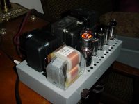
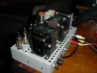
Finished the amp tonight, and... it worked - right off the bat. The gas tubes all fire, and the voltages are all extremely close to my estimates. I got 71v on the plate of the nuvistor, and a B+ at the output transformer of 245v. I ended up changing the last gas tube to an 0A3 type, because the primary of the phase inverter has a much lower DCR than I thought - 350 ohms. The resistor before the 0A3 must also change to a 6k-10w as well.
Speaking of the nuvistor, I have no oscillations, and no microphonics...
It sounds pretty good so far too. It's hard to tell in mono, but I don't hear anything bad so far other than a slight amount of residual 120Hz hum - but not an objectional amount. I'll have to track it down in the tweak stage of the project.
Anyway, I'll hook it up to the scope tomorrow and get some specs. Here are some pics in the meantime. I went for the industrial, 60's, Heathkit sort of look.
Attachments
- Status
- This old topic is closed. If you want to reopen this topic, contact a moderator using the "Report Post" button.
- Home
- Amplifiers
- Tubes / Valves
- A 10W ultralinear amplifier with unique features.