I REALLY hope i don't blow my transformer, it was expensive... also, I will always have the one 16-ohm speaker plugged it when the amp is on. I may put that 10-ohm 10-watter in there just as a precaution, because I really don't want anything to die in this build. I probably should have gotten cheaper parts to start out, but we'll see what happens. Anyone else have any suggestions based on that schematic? So far I am changing the 100-ohm pulldown resistor on the pentode to 2.2k or 2k, and adding a 330k 5-watt resistor from the 325 voltage point to ground as a discharge capacitor when the amplifier is off.
Sound good?
Sound good?
You are wasting a lot of power with a 10 Ohm dummy load. I recommend a higher value. I have heard of very few instances of blown transformers, so your concern isn't justified for the most part. If you are so worried, put in 50 or 100 Ohms and I am confident you will be safe. Unless lightning strikes, in which case all bets are off.
Haha alright, thank you, I may put one in later on after I get it up and working with the speaker in there. I also had yet another question about the power supply. Someone said I could reduce the noise on the B+ by putting a snubber network in there. My PT is a 275 volt output (so I get a bit less than 275*1.4) out of the diode bridge. How would I implement the snubber network to maintain the rest of the voltages there? I can consult my Morgan Jones book, but I'm unsure how to add one to an existing design without messing up the voltages.
I may avoid the snubber network if it gets too involved, I think the amp will sound fine without it.
I'll have to see what changing the pentode's resistor from 100 to 2000 ohms does also.
I may avoid the snubber network if it gets too involved, I think the amp will sound fine without it.
I'll have to see what changing the pentode's resistor from 100 to 2000 ohms does also.
Regarding the shunt resistor on the output, I recently built an AX84 20 watt amp for my son. It has a 10Watt 220R resistor permanently across the speaker outputs. With it in the circuit, with an 8 Ohm speaker, the parallel resistance is about 7.7 Ohms. This amp does, however, have a speaker connected with a jack, so it is likely someone may disconnect the speaker and turn it on. If your speaker is hard-wired to the amp, I probably would not worry about it.
The snubber capacitors are just small value capacitors across the rectifier diodes to help reduce switching noise. May be overkill on a guitar amp, but not too difficult to implement. It won't affect your power supply calculations, so no need to worry about it in PSUDII.
Cheers,
Chris
The snubber capacitors are just small value capacitors across the rectifier diodes to help reduce switching noise. May be overkill on a guitar amp, but not too difficult to implement. It won't affect your power supply calculations, so no need to worry about it in PSUDII.
Cheers,
Chris
Sorry the wording 'Snubber' isn't technically correct...I was thinking of something else.....actually it would be called a bypass cap.
Get four 10nF (Nano Farad), caps, non-polarized, running about the same voltage ratings as the diodes, soldered up in parallel on each one.
They will dampen out any oscillations that may creep up...plus will keep the EMF of the transformer in check.
Someone here advised using an extra long ground wire in case the wiring gets pulled out from the power cord?? Whats that!
Proper powering/wiring calls for an IEE socket on the back of the amp.
An IEE socket is a high current, high heat capable connector on the back. With a seperate detachable power cord this "yanking out" of wiring from the back of your amp makes this observation moot.
The IEE socket exists most commonly on high current kitchen appliances, Coffee pot, Popcorn maker, electric griddle?? Look for it..with the detachable cord.
HOWEVER! With the rough & tumble life of a guitar amp it might be annoying losing power to the amp every time you trip over your power-line while jamming.
__________________________________________________Rick....
Attachments
If you have a detachable power cord, then of course the "yanking out" rules don't apply. However there are specified rules for permanently attached power cords. Most guys who build little practice amps like the Champ don;t bother with detachable cords, so i didn;t assume that would be in use here.
To be clear, I didn't recommend anything extra long. I was merely, and in my own clumsy fashion, describing that (in a permanently wired power cord situtation) the ground wire is to be long enough that it would be the last wire to part if the strain relief failed. Nothing more cosmic than that.
Since you are not building this commercially, the point is moot. You don't have to meet UL certification or anything.
Granted our own designs don't have to comply with any rules.......but why take the chance? HV is very unforgiving & it doesn't discriminate who built it nor why.........it will just get-cha if your not careful.
Perhaps one could use the IEE plug with a tiny zip-tie around the cord....functioning as a lanyard of sorts. A semi-large force could "rupture" the zip-tie........acting like a sort-of force fuse.
Perhaps a zip-tie would be too strong(Even the small ones)......testing the concept would be in order.
Just throwing out ideas for ya!
_____________________________________________________Rick.......
An externally hosted image should be here but it was not working when we last tested it.
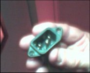
My AX84.com P1 for your reference. You can barely see the ceramic caps across the cheap diode bridge, on the left side of the board. on the bottom side, you can see the IEC receptacle with the ground lug bolted on the chassis.
By the way, it is better not to hardwire the speaker to the cab because it is nice to have it on top of the cab and tweak it while playing, service it etc. (my cab + 12 inch speaker may look like overkill, but the sound of this thing deserves it. My customer says that everybody that has listened to it has a big grin)
An externally hosted image should be here but it was not working when we last tested it.
By the way, dont worry about blowing up your speaker. 5 watts can't blow anything like a guitar speaker...
Attachments
Last edited:
Thanks again, I do plan on using the receptacle because I think it is easier to be honest, and I have a million of those power cords lying around. Also, I like the pictures but it is hard to see the diodes or capacitors in the diode bridge. I do understand what is being said about the caps across though. I can get some 500V 10nF ceramic caps easily.
I guess I had another set of questions.
12AX7 have three pins for their heater since its a dual triode. How do I hook it up?
Lastly, when building the power supply, should I mount it as far away from the audio circuit as I can in the chassis. I dont see a separate board in there for the power supply caps and resistors.
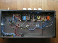
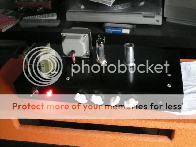
Yes,in general, power supply goes next to the power output section. Next the stage before output, etc etc, all the way to the input circuit, which is the furthest away from the power supply. On the photo, power supply on the left, 1st stage ECC83s on the right, If you follow the schematic, you'll see it is natural.
you really should have a look here
AX84.com - The Cooperative Tube Guitar Amp Project
you really should have a look here
AX84.com - The Cooperative Tube Guitar Amp Project
Last edited:
The 12AX7 does not have three heater pins because it is a dual triode, it has three heater pins because it can be wired for 12.6 or 6.3 volt heater supplies. Heaters in series for 12.6V, parallel for 6.3V. I agree with looking at AX84 site. The designs show chassis and component layout as well as the schematics.
Cheers,
Chris
Cheers,
Chris
Alright, thanks to everyone. I just realized that the Celestion V30 speaker I got is a 60-watt speaker. I won't be driving it anywhere near its capacity. I'm starting to worry about this!
The AX84 project looks great, I wish I knew about that before I destined myself to build the schematic I found! I'm sure I'll be happy with the design I chose as well.
The AX84 project looks great, I wish I knew about that before I destined myself to build the schematic I found! I'm sure I'll be happy with the design I chose as well.
- Status
- This old topic is closed. If you want to reopen this topic, contact a moderator using the "Report Post" button.
- Home
- Amplifiers
- Tubes / Valves
- 180 pF capacitor and other questions