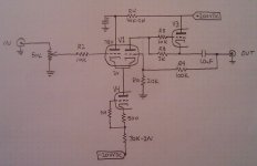
I successfully implemented a 12AU7A CCS that I pulled out of the Transcendent forum / Tube Audio Design chapter 7.
Works fine although I've not yet been able to determine if it sounds better or not. At the moment I'm only able to audition it connected to a 15 year old Headroom amp and some Grado SR-60's. I wired up a DPDT with the original 51K resistor on one pole and the 12AU7A on the other so I could A/B them. Clumsy but mildly effective. So now I'm ready to move to the next revision.
I've seen the thread on the Morgan Jones CCS board project and downloaded the documenation. I've also perused that section in Jones' book but I'm still missing some knowledge nuggets that would allow me to understand how I would apply that circuit to the grounded grid. For example, would I still need to use the negative supply? If not would I need an additional positive supply?
Rosenblit makes a comment in Audio Reality about using an FET as a CCS to eliminate the negative supply. What would that look like?
So I'm hoping some folks can set me straight with some guidance.
My goal is to just push this design somewhere else. Rosenblit's goal was cheapest cost and highest performance. I'm interested in expanding my knowledge by adding some moderate complexity while still keeping the performance high.
Attachments
CSS work best if they have some voltage to drop across them. How much depends on the design of the CSS. A Pentode or triode CSS needs a hundred volts negative supply. A bipolar cascode may need 10 V to 20V.For example, would I still need to use the negative supply? If not would I need an additional positive supply?
Check out the Salas low voltage shunt regulator thread. The use of a 2SK170 with gate tied to source is something they use to improve the design. That FET can operate with less than a volt drain to source. However, that limits the input signal to less than the current 2 volts before it "stalls" the Fet CSS or draws grid current. It's always about choices and compromises.Rosenblit makes a comment in Audio Reality about using an FET as a CCS to eliminate the negative supply. What would that look like?
HTH
Doug
Last edited:
I'm going back over the gg text and starting to look at the salas thread which so far is a bit out of my depth.
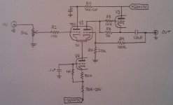
I'd like to try and replace both V3 and V4 with SS circuits. I just dug out my C4S kit manual. Since I have the boards and most of the parts, I might see if I can get that to work first.
Forgot a capacitor on my schematic.
I'd like to try and replace both V3 and V4 with SS circuits. I just dug out my C4S kit manual. Since I have the boards and most of the parts, I might see if I can get that to work first.
Forgot a capacitor on my schematic.
Attachments
I'm going back over the gg text and starting to look at the salas thread which so far is a bit out of my depth.
I'd like to try and replace both V3 and V4 with SS circuits. I just dug out my C4S kit manual. Since I have the boards and most of the parts, I might see if I can get that to work first.
Forgot a capacitor on my schematic.
The very simplest CCS can be used without a negative supply. Here's an example:
An externally hosted image should be here but it was not working when we last tested it.
It will work even better with valves other than the ECC83 since they have a greater bias voltage, allowing you to use a larger emitter resistor. Performance isn't spectacualr, but it should out perform what you have now.
I think you will be better off with a negative supply. If you rectify the 6.3V heater you should be able to get about 7V (with schotkey diode). Then you have a wider choice of CCS circuits and can use the 2 transistor cascode.
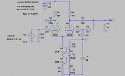
The illustration by Merlinb might work (even though my LTSpice is skeptical). Remember that when driving one grid of the LTP, the cathode voltage swing will be 1/2 of the input voltage. That leaves very little room for the CCS when using 12AX7. With the 12AU7 or similar it will work.
Svein
The illustration by Merlinb might work (even though my LTSpice is skeptical). Remember that when driving one grid of the LTP, the cathode voltage swing will be 1/2 of the input voltage. That leaves very little room for the CCS when using 12AX7. With the 12AU7 or similar it will work.
Svein
FWIW, Figure 2.48 (b) or (e) on page 134 of "Valve Amplifiers" Third addition has the circuit you are looking for. The emitter of the PNP would be attached to the cathodes of the Long tail Pair. (Grounded grid is a misnaming of the circuit by the designer).
I agree with Svein that the circuit shown in post 4 by Merlinb is not what I would recommend because it does not use a negitive supply.
Page 128 Figure 2.46 has a FET CSS between stages. Looking again Page 136 figure 2.49 has a great example of what you are trying to accomplish.
HTH
Doug
I agree with Svein that the circuit shown in post 4 by Merlinb is not what I would recommend because it does not use a negitive supply.
Page 128 Figure 2.46 has a FET CSS between stages. Looking again Page 136 figure 2.49 has a great example of what you are trying to accomplish.
HTH
Doug
Last edited:
Svein_B:
When you mention 12AX7 and 12AU7, to which valve in the schematic are you referring? All the valves in the schematic are 12AU7.
I was looking at, and simulating the circuit posted by Merlinb using ECC83(12AX7). 12AU7 will be OK, at least for line level signals.
The reference current for the diodes (or LED) should be taken from a reasonably high and stable voltage in order to have a constant current. Your 75V will be fine, with a suitable resistor to give a current of a few mA.
SveinB
Hey Ultra,
If you use a descent tube like 6H30 instead of the not-so-very-funny ECC82 you might get away without neg.supply as the tube has an Ug of 6.7V at normal currents. With a single BJT CCS the input will accept max 3Vrms. Better to go with a depletion-MOSFET and a negative supply of lets say 20V. With this tube(Ri 1-1,5k) you can also skip the SRPP to make the amp sound better.
If you use a descent tube like 6H30 instead of the not-so-very-funny ECC82 you might get away without neg.supply as the tube has an Ug of 6.7V at normal currents. With a single BJT CCS the input will accept max 3Vrms. Better to go with a depletion-MOSFET and a negative supply of lets say 20V. With this tube(Ri 1-1,5k) you can also skip the SRPP to make the amp sound better.

Merlinb:
In your example you have HT+ and V+. What range of voltage would V+ typically be? The 1.8V label suggests 12V or lower?
HT+ will be the usual, say 250V to 400V. V+ can also be anything; either a convenient low voltage supply, or R1 could even be connected to the HT, although that does mean more wasted power of course. When I built this circuit I used the DC heater supply for V+.
I built the circuit with 12AX7, but it should work even better with 12AU7, with suitable adjustment of the emitter resistor / base voltage.
FWIW, Figure 2.48 (b) or (e) on page 134 of "Valve Amplifiers" Third addition has the circuit you are looking for. The emitter of the PNP would be attached to the cathodes of the Long tail Pair. (Grounded grid is a misnaming of the circuit by the designer).
I agree with Svein that the circuit shown in post 4 by Merlinb is not what I would recommend because it does not use a negitive supply.
Page 128 Figure 2.46 has a FET CSS between stages. Looking again Page 136 figure 2.49 has a great example of what you are trying to accomplish.
HTH
Doug
Thanks. That's very helpful. I'll look at it tonight.
Revintage, thanks for that comment. Your mention of "SRPP" was an interesting clue.
Merlinb, that's what I was hoping you'd say. Looking at some of schematics in the salas thread and other CCS's, it was not yet obvious to me how they were connected.
- Status
- This old topic is closed. If you want to reopen this topic, contact a moderator using the "Report Post" button.
- Home
- Amplifiers
- Tubes / Valves
- help needed with grounded grid CCS upgrade