How to check bias
Could you please tell me how to measure the bias current on the FU50 version of the Sweet Peach? (Without a bias checker)
I have 2 good Fluke multimeters and not much else in the way of test equipment.
Also, I shorted the caps located on the selector switch board. (1C1 and 2C1) I was tempted to short out the series resistors and pull the ones to ground but ended up leaving them as is. What is their purpose? To make a stable input load?
Could you please tell me how to measure the bias current on the FU50 version of the Sweet Peach? (Without a bias checker)
I have 2 good Fluke multimeters and not much else in the way of test equipment.
Globulator posted in another thread "The russian GU50 tubes just plug straight in, remember to bias them to 50mA for best results. The output transformers on my Peach FU50 are fine, can't criticise them at all, they sound wonderful. My circuit is different to your though.
BTW you cannot use push-pull transformers in an SE design anyway, because the constant DC magnetic field upsets them. SE transformers are gapped to avoid this issue + they are actually bigger for the same power output IME. "
Also, I shorted the caps located on the selector switch board. (1C1 and 2C1) I was tempted to short out the series resistors and pull the ones to ground but ended up leaving them as is. What is their purpose? To make a stable input load?
Attachments
The input resistors have no purpose, just remove them.
To measure bias, measure the resistance of the cathode resistors (10R I think - but check), then use I = V/R and use the voltage across them at idle to check I.
If the cathode resistors are 10R then for 50mA you want to measure V = IR = 0.050 x 10 = 0.5V.
Watch out for the odd 400V + floating around on the tube base boards while you do this.
SLOOOOOLY upgrading my Sweet Peach FU-50
Our story so far; (need help locating good .1uf 400/600v caps)
I thought that I would post my upgrade path thanks to all the info here.
In order of the changes, here is what I have done
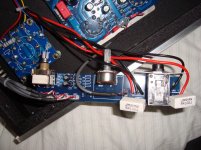
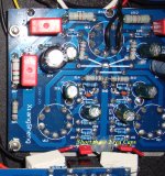
1. shorted out the 2 (wima?) input caps on the tube board (1C1 and 2C1) (pictured)
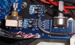
2.removed input resistors on selector/volume board and shorted caps (pic). of the 4 resistors, remove the inner pair and short the outer 2. Short the caps. This can be done from the rear of the board without removal if you have solder wick to allow pulling the 2 center resistors
At this point there was clearly an audible improvement. It's too hard to describe.
3. Rewired 6N1 socket for 6v paired filaments for 12AU7 tube. Added Tung Sol 12AU7W. Sound improvement was dramatic. Soundspace/imaging quite noticeable. "cleaner" sounding. Replacing the tube was by far the best change. I should have done it first so I could tell what the diff was when bypassing the input caps.
Unfortunately, I ordered .1uf 250v Wima caps to replace the big red box caps because one of them was labeled 250v and I believed it. I can't seem to find a source for the 400/600 volt caps. Once I get the new caps, I'll replace all the ones on the tube board. I already have the Jamicon 220uf but the .68uf wimas are in the mail somewhere.
Does anyone know the min voltage for the 4 red box "wima" .1uf caps? Any suggestions for adding parallel bypass caps to the stock ones while my search for replacement parts continues?
Question? Is there anything else necessary when reversing the 2 transformer red wires (B+ and FU-50)?, or do I just make the swap?
Thanks for all your help.
Our story so far; (need help locating good .1uf 400/600v caps)
I thought that I would post my upgrade path thanks to all the info here.
In order of the changes, here is what I have done
1. shorted out the 2 (wima?) input caps on the tube board (1C1 and 2C1) (pictured)
2.removed input resistors on selector/volume board and shorted caps (pic). of the 4 resistors, remove the inner pair and short the outer 2. Short the caps. This can be done from the rear of the board without removal if you have solder wick to allow pulling the 2 center resistors
At this point there was clearly an audible improvement. It's too hard to describe.
3. Rewired 6N1 socket for 6v paired filaments for 12AU7 tube. Added Tung Sol 12AU7W. Sound improvement was dramatic. Soundspace/imaging quite noticeable. "cleaner" sounding. Replacing the tube was by far the best change. I should have done it first so I could tell what the diff was when bypassing the input caps.
Unfortunately, I ordered .1uf 250v Wima caps to replace the big red box caps because one of them was labeled 250v and I believed it. I can't seem to find a source for the 400/600 volt caps. Once I get the new caps, I'll replace all the ones on the tube board. I already have the Jamicon 220uf but the .68uf wimas are in the mail somewhere.
Does anyone know the min voltage for the 4 red box "wima" .1uf caps? Any suggestions for adding parallel bypass caps to the stock ones while my search for replacement parts continues?
Question? Is there anything else necessary when reversing the 2 transformer red wires (B+ and FU-50)?, or do I just make the swap?
Thanks for all your help.
Attachments
Question? Is there anything else necessary when reversing the 2 transformer red wires (B+ and FU-50)?, or do I just make the swap?
Hmmm - why do you want to swap the wires around?
The 0.1uF/Red boxy caps should have a rating of 400V minimum, you can easily pick up suitable caps online, either from RS, Farnell, Digikey, Rapid etc. or ePay.
These ones look fine - I use them but I also bypass with Russian silver mica
")
CAPACITOR: 0.1UF/1000V Axial POLYPROPYLENE | eBay
Hmmm - why do you want to swap the wires around?
This thread has many references to reversing the xformer wires to preserve absolute phase. Reference "Hot sugar Mod" here.
http://www.diyaudio.com/forums/tubes-valves/163459-trying-make-sense-sweet-peach-9.html#post2170275
Well, having seen this thread and not being too handy, I decided on:
1- Sweat Peach FU/GU50 as arrived is about 30 times better sounding to me (IMO) than the end stage of my Marantz NR1602 (brand f*****g new, mind you).
2- I found out now that good stereo is better than mediocre x.x multichannel.
3- I've found that I now am listening to music more than I ever did after regrettable thereoaticallyselling my previous Marantz stereo thingy
4- Sweet Peach in delivered form is still better sounding than end stage on this Marantz 1602
5- While in theory it shouldnn't, it drives my B&W 603 s1 perfectly !
6- Most important: I've started to listen to music again.
That doesn't mean the Preach is perfect. I will replace the double triode for a proper one (6n6P) and I will replace all the caps as advised.
Nevertheless: need good sound on a budget: go for it !!
(no seriously. I'm finally starting to listen to music again due to the "opening up" by this amp. Even with the supposedly unsupported and low efficiency B&W 603 s1).
This thread has many references to reversing the xformer wires to preserve absolute phase. Reference "Hot sugar Mod" here.
http://www.diyaudio.com/forums/tubes-valves/163459-trying-make-sense-sweet-peach-9.html#post2170275
The "Hot Sugar Mod" is mine
.You only need to reverse the wires if you are doing the full mod, as the feedback works in the other direction.
If you simply reverse the wires you'll turn your peach into an oscillator!
thats what I needed to know! thanks
The "Hot Sugar Mod" is mine
You only need to reverse the wires if you are doing the full mod, as the feedback works in the other direction.
If you simply reverse the wires you'll turn your peach into an oscillator!
Sound quality of various caps?
I ordered an assortment of caps. Any opinions on which sound the best (replacing the .1 "WIMA" box caps
CORNELL DUBILIER
EPCOS
NISSEI
Philips
Arco Elmenco
Kemet
Wima
(I don't know why I didn't try Mouser first. I used to own/operate a brushless motor company for RC models and bought from them all the time)
Last edited:
6N3 Cathode resistor change
I am wondering what the benefit is to changing the 1k cathode caps on the 6N3 tubes to 2.2k I have printed out the entire thread, and don't find any rationale.
I know that I am coming into this thread about 2 years late, but I am trying to understand what the changes do.
I changed the 12AU7 cathode resistors to 2.2k from the "Modding the Sweet Peach" post 58. Should I change them to 1.5k as is recommended in a later post?
All the coupling caps are gone (little red ones on the tube board as well as the resistor network and caps located on the selector/volume/headphone board just after the selector switch. The 6N1 to 12AU7 valve change made the most difference. Unfortunately, I am a cancer patient on disability and can't afford a Mullard. The Tung-Sol seems pretty good. Any recommendations for a better sounding, but not ridiculously expensive 12AU7 Valve?
I am still waiting the the .1uf 600v caps and the .68 25v caps to bypass the 220 uf ones. I have everything else. If anyone has any "spare" high quality .1uf 600+V caps they would not mind selling, I would be grateful.
I also have GU-50 tubes en-route from Germany. at $4.50 each, I could not resist.
I am not comfortable with ripping out all the FB parts and using green LEDs, swapping xformer wires etc.
Is there a summary of what was finally settled on for the best sound?
Thanks
The different cathode resistors were just experiments in the bias current of the tube, which affects which part of the tube curves the audio uses.
Read up about tube load lines and look at the tube data sheets.
The 12AU7 needs heater re-wiring for it, so is not a direct swap.
People have found the 6n6p works well in there (just plug it in) so I'd try that.
Personally I did not find the curves looked that good though, but I didn't ever try it so have a go - it's much cheaper and easier than a AU7.
If you have already for the AU7 in (Tung-Sol are good!) then I'll have to have another look at the diagram - but 1.5k sounds a safe bet.
There are really 2 stages to the mods:
1) Change the caps etc and try a 6N6p or rewire heaters for an AU7.
2) Rebuild it completely.
Eventually I ended up at 2) - documented in the last few pages, and now I may even tweak that a little with some later ideas.
Cathode resistor changes
I made the 12AU7 swap (rewired for 6V w/ cut trace which was no big deal with a dremel.)
I chanced the 12AU7 cathode resistor to 2.2k as recommended in your post 58
I was just wondering what differences you heard changing the 6N3 cathode resistors from 1k (stock) to 2.2k. Changing to 1.5k can be easily done if the change to 2.2k was a mistake.
I am not really up for rebuilding the entire amp unless I rewired it into pentode mode but I was told that the transformers are not up to 18 watt output.
I could just make the resistor swap and listen, but sometimes these things are so subtle that I am not sure what I am hearing.
thanks again
You need to find out the voltage supply to the tube and the anode resistor, as I can't recall. If it's running at 380V with a 47K resistor then to balance the signal (i.e. midpoint) you need (380/2) / 47000 = 4mA, the ECC82 datasheet shows you need a -7.5V grid voltage.
So at 4mA that's 7.5 / 0.004 = 1875 ohms needed for the cathode resistors (2k). Can you measure the voltage from the anode resistor to ground and see what it is? I'm guessing 380V. Also measure the anode resistor as I am going from memory here.
Then use the calculations above and the ECC82 datasheet to see what you get. For 380V and 47k the cathode resistor is ideally 2k though.
The pentode mod requires metalwork etc - it's a very big rebuild, but the transformers handle the power well. It's less than 18W though
6N3 Cathode resistor change, cont.
These recommendations are for the 12AU7 valve I assume.
I was wondering what differences you heard when you changed the cathode resistor to 2.2k on the 6N3 valve? Is there a good replacement for that tube?
What do you call the mod described in post 58? I have made all the changes there except replacing the WIMA box caps. Replacements are still "in the mail"
Any other recommendations (leaving the feedback circuit basically intact)?
I havn't had a chance to make any voltage measurements. I'll do that soon for all 5 tubes.
Hi Morme,
The mod doesn't have a name so we'll have to call it Mod58 !
Yes my comments are for the ECC82, datasheet attached.
The biggest change (after the caps) was the ECC82, much better than the old mis-biased 6N1p.
I tried LED biasing but didn't like the sound, I was trying quite a few things. After a while the 6N3p tubes only being half used got to me, and Wavebourn told me they were poor for audio, and they are wired up in a weird way making substitution difficult so I redesigned the whole thing with new tubes and a much (much) shorter feedback path.
The main issue with the Mod58 is that it still uses the global feedback loop and the GU50 in triode mode, switching to pentode with proper feedback was a big jump.
Attachments
Señor Globulator, Do you by chance have a schematic of your final pentode version?
thanks for all your help
btw, I just ordered a new 12AU7A Amperex Globe Logo NOS made in JAPAN on Mullard tooling ribbed plates in original boxes 1970's. It's supposed to be a good sounding tube.
m
thanks for all your help
btw, I just ordered a new 12AU7A Amperex Globe Logo NOS made in JAPAN on Mullard tooling ribbed plates in original boxes 1970's. It's supposed to be a good sounding tube.
m
Some audio measurements
Hello all,
I recently got a defective Sweet Peach from a friend. It soon appeared that the sockets of the 6N1 and 6N3 are not of highest quality. Moving a bit the 6N3 in its socket solved the problem... But the quality of the whole stuff is not so fantastic, to say the least. It is a cheap product so let's not expect miracles.
By the way, no offense for the Chinese that are capable of building real jewels.
Still... As that the amplifier was fixed, I listened a bit to it. The first impression was that the sound was comparable to the inside of the amplifier. Really not impressive. Even disappointing.
Then, I made some reverse engineering (on a chinese design) to figure out what could be improved. So I did the following:
- Replace the 0.1uF input cap (supposed to be Wima) by high quality Panasonic 1uF.
- Replace the 0.1uF/250V (also Wima) by high Quality Audyn Plus caps.
- Replace the 4 cathode resistor decoupling electrolytic capacitors (220uF/35V) by Elna SILMIC II models with same ratings (that's all I had in stock), with 10nF MKP in parallel.
- Bypass the 220uF/35V electrolytic capacitor in series with the feedback network.
- Rebias the 2 FU-50 to 85 mA each (they were completely off: one at 90 mA and the other one at 55mA).
Listen again... At least I started to get a sense of a realistic sound stage and decent sound balance. But not yet to where I wanted to go. I was expecting these changes to have a lot more effects.
Then I fortunately found that thread and the post about the hidden 0.47uF capacitor on the POT / Selector board. I immediately bypassed these 2 caps and listened again.
Wow, what a difference now. It is becoming pretty interesting.
Note that I compare this little amp to a Cayin 500 with NOS tubes and to a heavily mod'ed 300B SE amp with modern Shuguang tubes (I found it on a second hand street market in Hong Kong...).
I also tried the 6N6 instead of the 6N1. The difference is not so obvious. I might have a slight preference for the 6N6 but not on all tracks. Female voice are a bit more pleasant with the 6N6. But the overall feeling of the amplifier of being in control of the speakers is not so great.
The gain of the 6N6 is lower than the one of the 6N1. The feed back loop does not play a significant role anymore and the output impedance of the amplifier is increasing significantly (though I did not measure it). That might explain what I heard.
I made some measurements of the amplifier with an Audio Precision analyzer, to see what I had in my hands.
First, I measured the effective power that could be obtained before the distortion shape changes dramatically. I obtained 6 Watts per channel.
If you accept to go up to 2% THD, the power is around 8 Watts.
With a speaker efficiency >90 dBSPL (mine are 91dBSPL), it is not an issue at all.
Preferably use a speaker impedance of 8 Ohms.
I made some THD measurements (I know that I should not talk about that when dealing with tubes, but I did...). I am giving all the plots for reference.
The frequency response
With the 6N1, it extends well over 20 kHz. The LF -3dB is around 5 Hz.
The 6N6 shows a loss of gain of about 2 dB (I tried 2 models, a chinese 6N6 from the same manufacturer than the 6N1 and NOS russian 6N6P). The treble extension is also slightly reduced (less feed back...). The bass goes 5 Hz lower.
The THD+N versus Frequency
I made the measurement for various FU50 bias level, from 50 mA to 100 mA.
I did not measure above that because the plate dissipation would be exceeded (40W) so nobody would want to use the amplifier like that.
I took the measurements at a power of 3 Watts, in a load of 4R7 with the impedance switch set to 4R.
The bias at 50 mA is really not good in terms of THD (2%).
The bias at 100 mA is decent at 0.6% but not much better that the bias at 80 mA at 0.7%. The H3 harmonics is getting more present with 100 mA.
I found 85 mA to be a very acceptable trade-off in terms THD vs power consumption.
With this bias, the sound stage is relatively accurate and stable.
With 85 mA, H3 is 20 dB lower than H2.
The big disappointment of that amplifier is the THD below 200 Hz.
It is increasing very fast when the frequency goes low. I suspect the output transformer to be responsible for that. That probably explains why I do not find this amplifier as good sounding as my 300B SE that has about the same output power (but OPT 4 times as big).
THD versus power
Not much to say, here.
THD increases regularly with power, which is normal. Still a bit high for my likings. You can see the 6W limits. I did the measurement with the 6N1 and the 6N6. The 6N1 has better THD figures because of the NFB playing a bigger role.
I did not change anything in the topology of the amplifier (it is not mine, after all). With better 6N3 and 6N1 (NOS russians?), the overall sound quality may improve. As I do not have these tubes available, I can't tell.
Bus, as such, with the 6N1 or the 6N6, the slightly modified Sweet Peach outperform most average transistor amplifiers I have heard.
For $300, we definitively can't complain.
Have fun with it.
Hello all,
I recently got a defective Sweet Peach from a friend. It soon appeared that the sockets of the 6N1 and 6N3 are not of highest quality. Moving a bit the 6N3 in its socket solved the problem... But the quality of the whole stuff is not so fantastic, to say the least. It is a cheap product so let's not expect miracles.
By the way, no offense for the Chinese that are capable of building real jewels.
Still... As that the amplifier was fixed, I listened a bit to it
. The first impression was that the sound was comparable to the inside of the amplifier. Really not impressive. Even disappointing.Then, I made some reverse engineering (on a chinese design
) to figure out what could be improved. So I did the following:- Replace the 0.1uF input cap (supposed to be Wima) by high quality Panasonic 1uF.
- Replace the 0.1uF/250V (also Wima) by high Quality Audyn Plus caps.
- Replace the 4 cathode resistor decoupling electrolytic capacitors (220uF/35V) by Elna SILMIC II models with same ratings (that's all I had in stock), with 10nF MKP in parallel.
- Bypass the 220uF/35V electrolytic capacitor in series with the feedback network.
- Rebias the 2 FU-50 to 85 mA each (they were completely off: one at 90 mA and the other one at 55mA).
An externally hosted image should be here but it was not working when we last tested it.
An externally hosted image should be here but it was not working when we last tested it.
Listen again... At least I started to get a sense of a realistic sound stage and decent sound balance. But not yet to where I wanted to go. I was expecting these changes to have a lot more effects.
Then I fortunately found that thread and the post about the hidden 0.47uF capacitor on the POT / Selector board. I immediately bypassed these 2 caps and listened again.
Wow, what a difference now
. It is becoming pretty interesting.Note that I compare this little amp to a Cayin 500 with NOS tubes and to a heavily mod'ed 300B SE amp with modern Shuguang tubes (I found it on a second hand street market in Hong Kong...).
I also tried the 6N6 instead of the 6N1. The difference is not so obvious. I might have a slight preference for the 6N6 but not on all tracks. Female voice are a bit more pleasant with the 6N6. But the overall feeling of the amplifier of being in control of the speakers is not so great.
The gain of the 6N6 is lower than the one of the 6N1. The feed back loop does not play a significant role anymore and the output impedance of the amplifier is increasing significantly (though I did not measure it). That might explain what I heard.
I made some measurements of the amplifier with an Audio Precision analyzer, to see what I had in my hands.
First, I measured the effective power that could be obtained before the distortion shape changes dramatically. I obtained 6 Watts per channel.
If you accept to go up to 2% THD, the power is around 8 Watts.
With a speaker efficiency >90 dBSPL (mine are 91dBSPL), it is not an issue at all.
Preferably use a speaker impedance of 8 Ohms.
I made some THD measurements (I know that I should not talk about that when dealing with tubes, but I did...). I am giving all the plots for reference.
The frequency response
With the 6N1, it extends well over 20 kHz. The LF -3dB is around 5 Hz.
The 6N6 shows a loss of gain of about 2 dB (I tried 2 models, a chinese 6N6 from the same manufacturer than the 6N1 and NOS russian 6N6P). The treble extension is also slightly reduced (less feed back...). The bass goes 5 Hz lower.
An externally hosted image should be here but it was not working when we last tested it.
The THD+N versus Frequency
I made the measurement for various FU50 bias level, from 50 mA to 100 mA.
I did not measure above that because the plate dissipation would be exceeded (40W) so nobody would want to use the amplifier like that.
I took the measurements at a power of 3 Watts, in a load of 4R7 with the impedance switch set to 4R.
The bias at 50 mA is really not good in terms of THD (2%).
The bias at 100 mA is decent at 0.6% but not much better that the bias at 80 mA at 0.7%. The H3 harmonics is getting more present with 100 mA.
I found 85 mA to be a very acceptable trade-off in terms THD vs power consumption.
With this bias, the sound stage is relatively accurate and stable.
With 85 mA, H3 is 20 dB lower than H2.
The big disappointment of that amplifier is the THD below 200 Hz.
It is increasing very fast when the frequency goes low. I suspect the output transformer to be responsible for that. That probably explains why I do not find this amplifier as good sounding as my 300B SE that has about the same output power (but OPT 4 times as big).
An externally hosted image should be here but it was not working when we last tested it.
THD versus power
Not much to say, here.
THD increases regularly with power, which is normal. Still a bit high for my likings. You can see the 6W limits. I did the measurement with the 6N1 and the 6N6. The 6N1 has better THD figures because of the NFB playing a bigger role.
An externally hosted image should be here but it was not working when we last tested it.
I did not change anything in the topology of the amplifier (it is not mine, after all). With better 6N3 and 6N1 (NOS russians?), the overall sound quality may improve. As I do not have these tubes available, I can't tell.
Bus, as such, with the 6N1 or the 6N6, the slightly modified Sweet Peach outperform most average transistor amplifiers I have heard.
For $300, we definitively can't complain.
Have fun with it.
Phono stage?
Hi all!
I think it is great that we have discovered this cheap Chinese tube amp that with minor mods, we can make it sing as well as $2000+ tube amps. The reason I'm considering this particular amp is that it has a phono stage built into it and I've been looking for an integrated tube amp with phono to save a bit of money and space! So, my question is, has anyone here tested the phono stage and does it sound at all decent?
Like a lot of Chinese amps, this one has major potential for around $300. I'm only a little worried about attempting some of the mods mentioned here, I have little hands-on electronic experience though I have read about the science behind these amps constantly, since I picked up my first tube amp several months ago. I now have one vintage Knight int. tube amp employing the 6GW8 power tubes (HARD to find), a small vintage Japanese pre-amp/phono stage with two 12AX7s (works although with obvious hum), and most recently, a new Chinese 6P1/6N2 amp ($250 total) that I thought would work with a turntable because of the high gain of the 6N2s (similar to 12AX7) and an input labeled "LP". I was wrong. I should've realized that it wouldn't work when there was no TT ground connection on the back. Anyway, I have my eye on this amp and this thread, now that I've found a tube amp that might actually do it all (TT, mp3, DAC, line-level amplification, etc.)
Thanks.
Following up from the comments by XavLNK on the performance, I concur with your thoughts about the limitations of the output transformer. Thanks for the extensive analysis, this is very interesting.
As per my comments in the other thread re distortion, if I just try to put more than a watt or two of sine wave through the EL34B peach below 100Hz you get serious transformer saturation. It is really very bad.
Also, I tried testing the amp using just the driver and output stage and it sounded like a guitar amp and looking at a 1kHz sine wave on the scope I could see a distorted wave shape at even moderate power levels. This was only occurring in the output stage and looked like 2nd harmonics. restoring the feedback and pre-amp tends to overcome most of this problem. I even tried swapping the EL34Bs for KT88s with no perceivable change, re-biased of course, keeping it around 55mA.
I am going to try it with some high quality transformers - I am waiting for a mate to lend me some. The problem is that the wiring is very hard to get to.
I can confirm that the primary of the transformers measures 5H inductance.
We can't expect more than this for the price and I am finding exactly what I would expect (and I wonder what is really hidden in the potting compound!).
- Status
- This old topic is closed. If you want to reopen this topic, contact a moderator using the "Report Post" button.
- Home
- Amplifiers
- Tubes / Valves
- Trying to make sense of the Sweet Peach