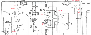
It has to be phase compensation of some kind. C1 combines with R4 to form a high pass pole. F3 for that pole is (sic) 1.6 MHz. That strikes me as being of little or no consequence at the frequencies of interest. Maybe it helps with ringing.
If one look at the erly schematic of ST20 with O/P 3921 - R5 is 100K and C5 is 20N( 0,02uF).
For the O/P 8778 on later models the R5 is 47K and C5 is 100N (0,1uF).
Could you explain why the values has been changed?
Gudmund
Different transformers have different parasitic capacitances and so need different compensation networks.
Shoog
Ok - but the 47K - does this value change the working point for ECC83 - or is the working line set by the cathode resistor used for ECC83?
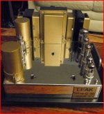
have you seen this wow looking rebuild on ebay...........
CLASSIC LEAK STEREO 20 VALVE POWER AMPLIFIER REBUILT on eBay (end time 23-Mar-10 23:10:53 GMT)
Thanks for the UL info.
This is really a complete rebuilt. - Chrome chassis - large capasitors and other "small" changes. It looks very nice. They are capable of fine handicraft in Glasgow.
The rebuilt of mine ST20 may, or have to, include new electrolytic capasitors. The visual look, from my point of view, need to be a little closer to the original layout. Same size of the capasitors and brown paint with letterprint. - have to see what it takes.
Gudmund
Over time, the parts manufacturers have increased the capacitance per unit volume of 'lytics, considerably. That fact makes replacing the innards of old filter caps. fairly easy. Use a tubing/pipe cutter to separate the base of an old 'lytic from the can. Dispose of the corrosive (IIRC, contains NaOH) contents, carefully. Clean the inside of the can. Stuff modern 'lytics into the can, solder the wires to the base (use "spaghetti" or heat shrink for insulation), and glue (epoxy, RTV, ...) the can to the base.
Over time, the parts manufacturers have increased the capacitance per unit volume of 'lytics, considerably. Dispose of the corrosive (IIRC, contains NaOH) contents, carefully. Clean the inside of the can. Stuff modern 'lytics into the can, solder the wires to the base (use "spaghetti" or heat shrink for insulation), and glue (epoxy, RTV, ...) the can to the base.
The capacitance per electrolytic volume has been increased - yes. For GZ34 the load capasitor is as high as 47uF- max rating for GZ34? - but what about the capacitance after the first 100R resistor? - would a higher value - say 100uF - give us some benefit in sound? - Could a parallel foilcap across the first or second psu-cap improve the sound?
Will be carefull with the (liquid?) NaOH - where are we supposed to leave such stuff? Thanks for the advice.
A new three soldertag 'lytic is normally already isolated with a gnd-tag - have to messure the old can to find the right (small) diameter for replacement.
Will be carefull with the (liquid?) NaOH - where are we supposed to leave such stuff?
Neutralize the alkali with vinegar (acetic acid). Sodium acetate is harmless and can be safely flushed down the drain. The electrolyte is a paste that may be partially or completely dried out. Dry or not, NaOH is dangerous, until neutralized by a weak acid. Wear thick rubber gloves and safety glasses until neutralization is completed.
The capacitance per electrolytic volume has been increased - yes. For GZ34 the load capasitor is as high as 47uF- max rating for GZ34? - but what about the capacitance after the first 100R resistor? - would a higher value - say 100uF - give us some benefit in sound? - Could a parallel foilcap across the first or second psu-cap improve the sound?
Keep C13 32 μF., to avoid overheating the power trafo. Increasing C12 to 100 μF. makes considerable sense, as this is the reservoir position. Don't bother with a bypass here, as modern industrial parts by Panasonic, Nichicon, etc. are MUCH better than OEM.
Increase C10 and C11 to 47 μF. Increased capacitance in those decoupling positions can't hurt and is likely to help. A 4.7 μF. Solen bypassing C10 and C11 might be of be benefit. Those parts supply the small signal circuitry.
Don't forget the cathode resistor bypass parts, C2, C7, and C8. As those parts are very much in the signal path, top quality is in order. Use Nichicon KZ series 'lytics. Increase C7 and C8 to 120 μF.
Neutralize the alkali with vinegar (acetic acid). Sodium acetate is harmless and can be safely flushed down the drain. The electrolyte is a paste that may be partially or completely dried out. Dry or not, NaOH is dangerous, until neutralized by a weak acid. Wear thick rubber gloves and safety glasses until neutralization is completed.
Keep C13 32 μF., to avoid overheating the power trafo. Increasing C12 to 100 μF. makes considerable sense, as this is the reservoir position. Don't bother with a bypass here, as modern industrial parts by Panasonic, Nichicon, etc. are MUCH better than OEM.
Increase C10 and C11 to 47 μF. Increased capacitance in those decoupling positions can't hurt and is likely to help. A 4.7 μF. Solen bypassing C10 and C11 might be of be benefit. Those parts supply the small signal circuitry.
Don't forget the cathode resistor bypass parts, C2, C7, and C8. As those parts are very much in the signal path, top quality is in order. Use Nichicon KZ series 'lytics. Increase C7 and C8 to 120 μF.
Shall use the weak acid you suggested for neutralization! - remembered some about the alkali / acid relations after you mentioned this.
- Really think that we have achieved something in this thread. - shall try to find the Nichicon KZ capasitors.
- Did you notice any difference in performance together with the mentioned changes in ST20?
Do you have further suggestions for ST20 improvements?
- Have been wondering why the power transformer went that hot at normal drive by use of 47uF as C13!! - was difficult to imagine that H.J.LEAK LTD. company should have used such undersized powertransformer for public sale. - most of the heat might be the result of glow for GZ34 and approx. 4 A?? - what is your experience?
Gudmund
Increase C10 and C11 to 47 μF. Increased capacitance in those decoupling positions can't hurt and is likely to help. A 4.7 μF. Solen bypassing C10 and C11 might be of be benefit. Those parts supply the small signal circuitry.
Don't forget the cathode resistor bypass parts, C2, C7, and C8. As those parts are very much in the signal path, top quality is in order. Use Nichicon KZ series 'lytics. Increase C7 and C8 to 120 μF.
- Could only find Nichicon KZ 100uF/100V radial and 220uF/100V. What do you suggest we do? - is 220uF too much for C8 and C7? - C2 may have to be close to the stated value of 50uF// 2K2 - working with the FB signal?
Make C2 100 μF./25 WVDC. Make C7 and C8 220 μF./50 WVDC.
How deep do the speakers you plan to use with this amp go? We really should provide some protection against O/P trafo core saturation. That's done by rolling infrasonic noise off at the unit's I/Ps. Installing 68 nF. caps. instead of wires between the RCA jacks and the voltage amplifier triodes' grid circuitry sets F3 for the unit at 23.4 Hz., when combined with the 100 KOhm value for R1 previously discussed. A well matched pair of Soviet surplus paper in oil (PIO) parts would be superb here. BTW, the lowest note a double bass can produce is 31 Hz.
How deep do the speakers you plan to use with this amp go? We really should provide some protection against O/P trafo core saturation. That's done by rolling infrasonic noise off at the unit's I/Ps. Installing 68 nF. caps. instead of wires between the RCA jacks and the voltage amplifier triodes' grid circuitry sets F3 for the unit at 23.4 Hz., when combined with the 100 KOhm value for R1 previously discussed. A well matched pair of Soviet surplus paper in oil (PIO) parts would be superb here. BTW, the lowest note a double bass can produce is 31 Hz.
Make C2 100 μF./25 WVDC. Make C7 and C8 220 μF./50 WVDC.
How deep do the speakers you plan to use with this amp go? We really should provide some protection against O/P trafo core saturation. That's done by rolling infrasonic noise off at the unit's I/Ps. Installing 68 nF. caps. instead of wires between the RCA jacks and the voltage amplifier triodes' grid circuitry sets F3 for the unit at 23.4 Hz., when combined with the 100 KOhm value for R1 previously discussed. A well matched pair of Soviet surplus paper in oil (PIO) parts would be superb here. BTW, the lowest note a double bass can produce is 31 Hz.
- Have already ordered both values Nichicon muse KZ 100uF and 220uF at 100V.
- by normal sound level AR11 is used. - know that we only have approx.12W from the ST20, but sufficient for AR11 in spite the low power. - like the low-low bass sound.
When you say 68nF from the RCA jack - you mean CR filter = 0,68nF followed by 100K? 23,4Hz should do it!!
The PIO from Soviet - the green ones with glass-surface?
Thanks
Gudmund
- by normal sound level AR11 is used. - know that we only have approx.12W from the ST20, but sufficient for AR11 in spite the low power. - like the low-low bass sound.
Thanks
Gudmund
Hi Gudmund,
My stereo 20 drives occationally AR3a - The used Siemens EL84 gets very hot and burns black and grey inside and I will not recommend the stereo 20 for such heavy driven speakers. It is much easyer for the ST20 with JBL L96 if you like vintage sound.
Best regards
KJ
Service Note for Leak Power Amplifiers:Stereo 20, TL25 Plus, TL50, Stereo 50 & 60
Leak amplifiers are quality units and harmonic distortion readings are usually better than the manufacturer's numbers. However, harmonic distortion may appear due to a defective .1 mfd capacitor in the phase inverter circuitry. It is connected to pin #2 on the ECC83 tube. It reads just a few millivolts to ground, which is enough to upset the balance of the inverter tube. The remedy is to replace the said capacitor with a Metalized Polyester .1 mfd @ 630 CDC, which has exceptionally low leakage. This applies to Leak power amplifiers: Stereo 20, TL25 Plus, TL50, Stereo 50, & Stereo 60.
Hy Bloom CEO, Retired
Soundmaster Ltd., Ottawa, Canada
Harryh .bloom @ gmail. com
Drop R21? GZ34 can't load 64uF
Drop solder R21? ....according to what "LeakStereo20.dk" says, GZ34 can't handle to load 64uF....32uF is the limit. Read:
https://sites.google.com/site/httpstubeamp/
I have just done a refurb on a leak st20 (25%UL) it looks like they were trying for a more single end like treble. see link
Drop solder R21? ....according to what "LeakStereo20.dk" says, GZ34 can't handle to load 64uF....32uF is the limit. Read:
https://sites.google.com/site/httpstubeamp/
- Status
- This old topic is closed. If you want to reopen this topic, contact a moderator using the "Report Post" button.
- Home
- Amplifiers
- Tubes / Valves
- Leak stereo 20 modification