Figure 1000 watts at 25% efficiency and 2 channels. that's 8000 watts = 27304 BTU/Hr or about 2.5 tons of cooling. on the water side, at a 10 degree split (80 degree entering water, 90 leaving) you would need 5.5 gallons per minute of cooling water. This is peanuts with respect to heating the pool. On the air side, you would need about 2000 cfm to maintain 105 degrees in the amp enclosure. You could do that with an old 5 ton air handler cooled with the pool water. This would work, but straight water cooling (without air cooling an enclosure) would certainly be quieter.
You could likely find an old chilled water fan coil for the cost of scrap that would certainly do the trick. My gut tells me that a 4 row coil would do the trick since it wouldn't have to do any latent cooling (dehumidification).
This would be a cool project to try.
You could likely find an old chilled water fan coil for the cost of scrap that would certainly do the trick. My gut tells me that a 4 row coil would do the trick since it wouldn't have to do any latent cooling (dehumidification).
This would be a cool project to try.
Like anything this big and complicated it is best to prove the concept on a small scale before building a big expensive device containing a conductive liquid, and a lot of voltage. I remember a rather spectacular display of fire, smoke, and steam when a water leak occurred in a large CO2 laser at work that ran on 25KV. I was the repair guy that had to fix it.
It would seem that the first nut to crack would be to find a suitable tube and method to transfer the heat dissipated to a suitable liquid. The OPT's that I have are 1250 ohms CT. This pretty much rules out HV transmitting tubes. My preference would be toward sweep tubes, maybe 6 to 8 per channel, with a target power output of 500 WPC, and an efficiency of at least 50%. Higher efficiency might be realized using screen drive, or some other yet to be proven methods.
I can remember some experiments back in high school with some metal 6L6's running upside down in a fish tank full of water making some stupid amounts of power before the water started to boil, but I never determined the life expectancy of the tubes because something else always blew up. It safe to assume that this isn't the right way to go, and metal 6L6's aren't free like they were in high school electronics class.
Since most of the "heat" emitted by a vacuum tube is actually radiated, it would make since that you could make a water cooled heat absorber. Sort of a heat sink in reverse. Some experiments are in order.
Sweet Kilowat Light show
The video is awesome with the nasty mercury rectifiers flickering away. After I finished the 2001RB Amazon.com: Gallien-Krueger 2001 RB Bi-Amp Bass Amplifier (Dual 540 Watt/1080 Watt Bridged): Musical Instruments (not a plug, I haven't worked there for years) I bought a pair of 3-500Z's to build a fat tube amp head. I figured to ground the grids like on the Eimac data sheet for an AF amplifier and cascode them to bi-polar transistors back to the diff pair. Today I'd still cascode them, but to a pile of 6L6's or something in parallel below ground. I still pull the 3-500Z's out once in a while to cuddle.
Regards
Today I'd still cascode them, but to a pile of 6L6's or something in parallel below ground.
I would try a P channel mosfet follower with its drain grounded and the source wired to the cathodes. It works on the 833A's.
After I finished the 2001RB.....
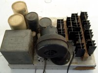
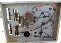
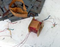
Well if we are to mention SS projects, I have been cleaning out my accumulation of "stuff" when I found some projects that I saved from way back in my past. I came upon this "booster amp" that I built in high school. It would have been late in 1969. Now understand that my construction skills sucked then, and my tools consisted of a hammer, a scrwedriver, a drill, and a nibbler tool. My budget was below zero so all of the components were obtained on barter. I traded my time for some parts. I knew that I needed a trifilar driver transformer, so I made my own. The circuit was patterned after the output stage of a Heathkit SS amp. There are 6 mystery transistors running on a B+ of 100 volts. We drove this with a small solid state amp and we were getting about 400 watts into a 2 ohm load. It was used for outdoor concerts and saw duty most weekends for about a year.
Attachments
Yeah, where's light there's shadow. I'm still wishing, my university would approve of my plan of a three month holiday starting ... well, now, so I could take a look at Florida's spring weather with my own eyes.. Too bad.
Well, regarding to MJ, 50% of the tube's heat is dissipated via radiation, while about 50% of the energy is heating the glass tubing. If your are going to watercool, I guess the roughs of the "fishtank"-approach are actualy the smartest way to do it. Put the tubes directly into the water upside down and you save complicated cooling units with less efficiancy. A couple of legris connectors, a bit of anti-freezing agent against microorganism growth and a clean, used car radiator + fans + pump should do the rest of it. I have been using a water cooler for my PC for quite some time now and it's basicaly the same thing, just a little bigger.
Well, regarding to MJ, 50% of the tube's heat is dissipated via radiation, while about 50% of the energy is heating the glass tubing. If your are going to watercool, I guess the roughs of the "fishtank"-approach are actualy the smartest way to do it. Put the tubes directly into the water upside down and you save complicated cooling units with less efficiancy. A couple of legris connectors, a bit of anti-freezing agent against microorganism growth and a clean, used car radiator + fans + pump should do the rest of it. I have been using a water cooler for my PC for quite some time now and it's basicaly the same thing, just a little bigger.
I will just place the amp outdoors and be done with it, just use it when the weather allows it. The enclosure would still be a challenge to design and if you got tired of it you could sell the amp...plenty of Canadians in this forum.
A big fan makes too much noise, not to mention the air currents inside the house. Water and electricity scares me...I know you're an engineer but still...too much trouble.
I admit my idea sounds boring, you won't see the tubes, etc.
Your pics tell me you're an alpha male so you would probably discard this idea anyway. I know you love the dangerous side of it, well, good luck on your project.
Yea tubelab - Stick it outside, unless this is a design challenge that you just really want to do, (kind of sounds like it is). Design a box that the amp could live in just on the other side of a wall that is weather proof. Wait a minute. If it is 90-100 outside you still have to do some serious cooling. I keep forgetting that it is hotter outside than in. I have a diferent perspective, living in Wa. state.
1000 watt tube amp
When I was in high (low) school, I knew the guys in the "Civil Patrol" group.
The idea was that if the nasty Rooskyies came over, they would get out all the emergency gear and set up the PA system for yelling things like "Run from your Bank!" Etc. and other stuff.
There was this small room with all the emergency gear.
One of the interesting items was the 1000 watt tube amp for the PA system with horns on stands etc. so someone could yell at the frantic masses.
I wish like heck I had a picture of it. I used to go to all the military surplus stores in LA that had tons of radio gear.
FAIRadio.net Home Page is Fair Radio sales in Lima Ohio, still selling.
I remember the amp was a large box, about 30" by 20" by 12" high.
It had something like twelve 811a transmitting tubes in it, it's own gas generator and a group of horns, mike all that.
Now I wish I had taken pics of all that "secret stuff" in the old "Civil Patrol" bunker.
We were going to take the PA to the water tower, and play the soundtrack to "War of the Worlds" at like 2:00 AM, just to add a leetle excitement to the area.
So yes, using Horizantal sweep tubes, or something like 811s, no problem
i also have a small pile of old Radio books. One of them has the complete schemo and pictures of a AM radio transmitter. It used a 5000 watt, watt cooled triode. There were, or still are up to 20Kw triodes that have water connections in the top and bottom so water can be forced down around them so they stay cool.
KFI and some of the old AM stations still use them
It is Fair Radio Sales Company Inc., the evil Mac was sticking it's nose in while I was typing.
Look up how AM transmitters were built.
There still is a transmitter for sending to subs somewhere around Texas, Gulf of Mexico?
It has tubes so big they are rooms you walk into, all underground, so the low frequency waves travel into the ocean better.
Look up how AM transmitters were built.
There still is a transmitter for sending to subs somewhere around Texas, Gulf of Mexico?
It has tubes so big they are rooms you walk into, all underground, so the low frequency waves travel into the ocean better.
It would seem that the first nut to crack would be to find a suitable tube and method to transfer the heat dissipated to a suitable liquid. The OPT's that I have are 1250 ohms CT. This pretty much rules out HV transmitting tubes. My preference would be toward sweep tubes, maybe 6 to 8 per channel, with a target power output of 500 WPC, and an efficiency of at least 50%. Higher efficiency might be realized using screen drive, or some other yet to be proven methods.
Tubelab
I was thinking of 6 x 807's or KT88s i have have found some very nice OPTs wide bandwidth and i think good for about 300 W.
I don't have the tubes. Where do i get RELIABLE matched multiples like this? The 807's are a more affordable option but may be harder to work with (stabilise).
Are the Russian 807's OK?
What are your thoughts?
The problem with DI water is that anything with a high enough resistance is going to be aggressive enough to corrode all metals but stainless steel
The corrosivity of DI or distilled water comes from the dissolved CO2 which forms carbonic acid in the water. Other gases could be dissolved to produce other acids but only CO2 is naturally present in the atmosphere enough to dissolve in significant amounts unless you're near a coal plant...
I believe the H2CO3 can be scavenged from a closed system using a resin exchange process (like in a water softener) but I don't know the resulting conductivity. Most recommended treatment, such as adding CACO3 etc. will increase the conductivity.
I would probably not try anything with energized parts in contact with the coolant at home.
The problem with DI water is that anything with a high enough resistance is going to be aggressive enough to corrode all metals but stainless steel
??????
dissolved CO2 will cause a problem but then it would not be truly deionized. We use RO/DI reverse osomosis and then DI'd. No dissoved gasses. The system should be closed to prevent contamination with air, dust.
Certainly it shouldn't be done at home, but it is done all the time with industrial equipment and settings. We have it flowing through copper, stainless and some aluminum components. We do not flow it through iron or galvanized. Reason being is that they are magnetic and significantly effected by the fields. Iron will literally boil the water in the pipe.
If corrosion is an issue there are inhibitors that can be added.
The problem with the DI water is that once it leaks, it will contaminate and likely become conductive...NOT GOOD
If that doesn't scare you then consider that our xfmr secondarys run around 1000V and we run plain old cooling water from the cooling towers through those cables.
Last edited:
This is a truly interesting thread. I used to work as a maintenance spark at a local induction heating company. We had some 50KW and 75KW induction heating machines made by Delapina in the 50s/60s they used a water cooled triode. I cant remember the number, they were the size of a waste paper bin and dead ones were a good door stop. The heater was 6V 100A and the water was flowing through the glass to directly cool the anode. We used to be able to get replacements (extremely expensive) so I think they are still made. This was a round 1996. The main trouble was that the whole system had to use deionised water because they had no heat exchanger. We modified a couple to allow the main system and cooling tower to use normal water. They were a very pretty tube, I wish I had grabbed a dead one before I left. None of the more modern ceramic stuff, just glass and if you overode the interlocks, the brightest heater you have ever seen.
Cheers Matt.
Cheers Matt.
The biggest brute tubes Eimac made were cooled with water vapor. Water vapor still has a pretty high specific heat and you can heat it up until you worry about the stainless steel holding it melts. The problem with liquid water in high power cooling is it rattles the tube as it boils. As I recall the biggest tube I saw in the catalog had a plate dissipation of 1.7 megawatts.
We used 12 megohm DI water at a Motorola plant where I used to do work in Arizona. It would corrode all metal tubing but 316 stainless steel. we used polypropylene tubing to move it through the plant as 316 stainless tubing was insanely expensive in the diameters we were using.
We used 12 megohm DI water at a Motorola plant where I used to do work in Arizona.
We used to have a DI system in Plantation too. It was all plumbed with plastic tubing of some type. There were about 15 tanks all plumbed in series. The maintenance guy referred to them as "filters". Each one had a neon lamp indicator on the top. A fresh set of filters had no lights lit. The first one would light up in a few days. Once about 3 or 4 lights lit up the first half of all of the filters were changed. The next time a few lights lit up all of the filters were changed. The DI water was used in the manufacture of quartz crystals and microelectronic modules.
I have a friend who used to work there too who has built a moonbounce transmitter. It runs 6 X 2C39 tubes (external anode) with 1800 volts on the plates. The plates are screwed directly into an aluminum heat exchanger which is cooled by water. He says that he changes the water every month or so.
The neon lights have since been replaced with LED's. The mho meter is about an inch square and runs on a 9 volt battery. On our HV stuff we do run cartridge filters to keep the conductivity down.
I should add we do have galvanic isolators in our system. These are to prevent a galvanic couple from forming between dissimilar materials. Other than that no issues.
I should add we do have galvanic isolators in our system. These are to prevent a galvanic couple from forming between dissimilar materials. Other than that no issues.
- Status
- This old topic is closed. If you want to reopen this topic, contact a moderator using the "Report Post" button.
- Home
- Amplifiers
- Tubes / Valves
- Monstrous 1kW amp!