Hi there,
I am looking for some help to define the most appropriate tube to use at the input stage of an hybrid amplifier.
Let me give you the topic : I want to make an amplifier whose input stage is a differential stage using two triodes, ouput stage will be all bipolar.
I want to have a 40Vpeak on one of the triode plate for a single input of 1V peak.
So I need at least 40 for amplification.
The issue is that I don't want to use high value load because I may have some loading from bipolar buffer. If I could stay with something like 50k, I would be happy.
Do you have any idea how to struggle with those spec :
- B+=150V
- Vp with no input signal = 100V (to be able to have +/-40V...)
- Ip=5-10mA max (I don't want to add cost on power supply, made from 50V Transformer with multiplier...)
-µ>xx
-Ra>50k
- Input signal may be 1-2V peak max (I will reduce gain if 2V, but no grid current for this signal!)
Don't want you to work to much! Perhaps you already have the ideal solution?
I am evaluating now 12AT7 on PSice, it looks quite good.
But I have been advised that it has no microphonie protection.
Ohh... last but not least, I would prefeer a tube that is always on production.
All that seems easy?
Thank you for any help!
Regards
Laurent
Amplification of 40x with one input driven is tough.
A diff-amp (LTP with a CCS tail) will have a gain of 1/2 of compared to a single common cathode stage.
With 12AT7 I can get about 30x, which leaves you 3dB short of your target.
12AX7 could get the gain you want, but not happy with low impedance loads.
SveinB
A diff-amp (LTP with a CCS tail) will have a gain of 1/2 of compared to a single common cathode stage.
With 12AT7 I can get about 30x, which leaves you 3dB short of your target.
12AX7 could get the gain you want, but not happy with low impedance loads.
SveinB
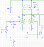
As you're mixing sand with your glass anyway, you could consider using a bipolar cascode as a telescopic cascode load for the tubes in the diff pair. That way you can get gains very close to the rated amplification factor (mu) of the input tubes. This also loads the triodes with something that's very close to an ideal current source so they should operate quite linearly.
6J5 will give you a gain of about 20. I think the ECC83 (12AX7) would give you a gain of about 100.
If you run a tail current of, say 10 mA, you set up the cascode as a current source delivering 5 mA. There's a blurb about BJT cascoded differential pairs in Morgan Jones' book.
~Tom
6J5 will give you a gain of about 20. I think the ECC83 (12AX7) would give you a gain of about 100.
If you run a tail current of, say 10 mA, you set up the cascode as a current source delivering 5 mA. There's a blurb about BJT cascoded differential pairs in Morgan Jones' book.
~Tom
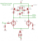
A pair of D3a in triode with choke or gyrator loads and a CCS tail will get you a voltage gain of 40x per side or 80X side-to-side when driven from one side (also maybe 12HG7 in triode)
There is an interesting hybrid inverter discussed in a recent thread
http://www.diyaudio.com/forums/tubes-valves/160776-phase-splitter-idea-2.html#post2077262
Michael
There is an interesting hybrid inverter discussed in a recent thread
http://www.diyaudio.com/forums/tubes-valves/160776-phase-splitter-idea-2.html#post2077262
Michael
Last edited:
Laurent,
The 150 V. B+ limit combined with the halved gain inherent to driving only the inverting I/P of a differential gain block makes things very tough. I think you are going to have fits trying to "shoehorn" a triode into this role. However, all is not lost. The EF86 small signal pentode will provide the gain needed, with some help from "sand". Buffer the resistively loaded anodes with DC coupled FET voltage followers. The capacitances of the ZVN0545A are quite small and you may be able to avoid a cascode in the follower.
I hope you are already contemplating a bipolar PSU. You will need a negative rail to energize the necessary tail CCS and provide compliance with the I/P signal.
Thank you All, I like that web site with all possible contributions!
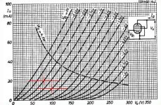
12AX7 : Yes, I LSPICEd it and I could see what spec curves shows : input voltage will be limited to less than 1V if high current is to be expected.
Cascode with BJT : you know what? I tested it. But I can't understand if this is equivalent to load Tubes with current source or not. In fact, as load impedance is low, we are not in best case for distorsion, we need high impedance compared to Ri (Ra/Ri should be high for low distorsion). Thus even if that provides high gain, even if Tube is forced in constant voltage current source, I don't know yet if distorsion figure is better or not. To be investigated!
Penthode : yes I agree, gain will be higher. But before commited myself to accept using other thing than the sacred triode, I would prefeer to finish with the triode. How would I face real audiopile with a penthode as input stage??? ;-)
Didn't have yet time to follow the link you provided. Some homework to do!
Thank you for your help. Any comment welcome!
regards
Laurent
As a practical matter, I haven't had any issues with microphony of 12AT7 in the input stages of my amplifier.
If the input stage has another stage following it, and your source doesn't mind some input capacitance, a 12AX7 run at 0.75-1 mA per side will get you what you want. The issue will be bandwidth- the 12AX7 will have a rather high output impedance, and this will interact with the input capacitance of the next stage.
If the input stage has another stage following it, and your source doesn't mind some input capacitance, a 12AX7 run at 0.75-1 mA per side will get you what you want. The issue will be bandwidth- the 12AX7 will have a rather high output impedance, and this will interact with the input capacitance of the next stage.
Penthode : yes I agree, gain will be higher. But before commited myself to accept using other thing than the sacred triode, I would prefeer to finish with the triode. How would I face real audiopile with a penthode as input stage??? ;-)
Many of the past's "giants" used pentodes at the amp's I/P. We are NOT smarter than Hegeman, Recklinghausen, Hafler, and other luminaries were. You are boxed into a corner by that 150 V. B+ rail limit. Differential gain blocks should be resistively loaded, with a constant current sink (CCS) in the tail. Even the previously mentioned 6922 cascode needs more Volts than you are willing to use. Remember, a voltage drop occurs across the load resistors. The EF86 is both highly linear and very good sounding. Quite a few triodes can't come close to the sonics the EF86 produces.
IMO, the EF86 is as close to perfect as you will get, for this particular job. It's in production, sounds good, works well at modest anode voltages, and draws a low IB.
Have you given thought to the GNFB loop OTL BJT "finals" imply? Are you planning on MCPs? Are you certain that a DC offset will not be present, at the amp's O/Ps?
Cascode with BJT : you know what? I tested it. But I can't understand if this is equivalent to load Tubes with current source or not. In fact, as load impedance is low, we are not in best case for distorsion
The anodes of the tubes "look into" a collector. So they should see a load resistance that's fairly high. However, if the diff pair is not loaded evenly by the subsequent circuit, the distortion will suffer.
If I only need one of the two outputs from the diff pair, I find that putting in a "dummy load" on the unused output will be beneficial to distortion performance. Usually I use 220 nF + 470 kOhm as coupling cap, grid leakage resistor on a following stage. All that's needed is a replica of the 220 nF + 470 kOhm to keep the diff pair evenly loaded.
In PSpice, I had to use actual BJT current sources as the ideal ones created a fairly unrealistic DC operating point. You may have to do the same in LT Spice.
~Tom
Attachments
Tom's setup uses a 375 V. B+ rail. Once the 150 V. B+ limit is established, the EF86 (IMO) sticks out like a sore thumb.
True. But the anode voltage on the 6J5's is only about 25 volts in my sim. This is obviously not a desired operating point. But by tweaking the ratio between the two current sources, you can move the operating point. At one point I was running with 60-ish volts on the anodes and distortion numbers on the order of 0.01 %. I don't see any issues with doing that on a 150 V rail. You only need a few volts across the cascode for it to be happy.
~Tom
Have you looked at Allen Wright's PP-1C? It uses 6922s in a cascode LTP. Plenty of Gm, low OP impedance, 25k plate loads and that tube will run with low plate voltage.
Thank you for the recommandation.
Didn't have the opportunity to find the schematic. Do you have a copy of the portion of interest? Is it all tube or hybrid?
The EF86 is both highly linear and very good sounding. Quite a few triodes can't come close to the sonics the EF86 produces.
Have you given thought to the GNFB loop OTL BJT "finals" imply? Are you planning on MCPs? Are you certain that a DC offset will not be present, at the amp's O/Ps?
I will take some time to consider EF86, the curves look nice.
The final BJT stage will be a follower, gain may be added by changing a resistor. I will try various gain/feedback ratio during design phase.
I am already considering a DC servo. Not just because the BJT may introduce offset, but because the complete path (from input RCA to speaker) will be DC coupled. Goal is no Cap and no transformer.
I am also considering differential stage as I want to be compatible with XLR. But conflict with DC servo and feedback is to be solved (after all, this is not a copy paste but a study!)
I am not familiar of the "MCPs". I suppose it is not "Micro-Channel Plate amplifier" as I find on google?
...However, if the diff pair is not loaded evenly by the subsequent circuit, the distortion will suffer.
If I only need one of the two outputs from the diff pair...
In PSpice, I had to use actual BJT current sources as the ideal ones created a fairly unrealistic DC operating point. You may have to do the same in LT Spice.
~Tom
I was considering a circuit of this kind. I suppose that the resistive part of the load is the connected circuit? Thus gain may change according to level no? I wonder how linear a high value load stay if connected circuit is active and bipolar. Did'nt investigate much up to now.
I will need both output of differential stage for the output buffer, so symetric loading will not be an issue.
I haven't heard a triode solution except D3A yet...
at 80V p-k you have enough headroom for a gyrator
I put in a CCS tail; you might do something different.
Also if the loads are symmetric you can replace the 2nd D3A with another MOSFET, properly biased of course.
at 80V p-k you have enough headroom for a gyrator
I put in a CCS tail; you might do something different.
Also if the loads are symmetric you can replace the 2nd D3A with another MOSFET, properly biased of course.
Attachments
I was considering a circuit of this kind. I suppose that the resistive part of the load is the connected circuit?
Correct.
Thus gain may change according to level no? I wonder how linear a high value load stay if connected circuit is active and bipolar. Did'nt investigate much up to now.
The gain of any amplifier will always depend on the load impedance (along with source, input, and output impedances). No news here. But with a light load (470 kOhm in my case) the load impedance will only have a small impact on the overall gain. The gain will not depend on signal level.
The issue is that the differential amp has very high output impedance. As the output impedance and load impedance form a voltage divider, a low load impedance will reduce the gain dramatically. There are different ways of addressing this. One is to use a cathode follower (or source/emitter follower). Morgan Jones does this in his Crystal Palace Amp. The cathode/source/emitter follower has very high input impedance so it doesn't present very much load on the preceding stage. At the same time, it offers low output impedance, hence, has a good capability for driving a heavy (low impedance) load.
I will need both output of differential stage for the output buffer, so symetric loading will not be an issue.
Sweet. Just make sure that the two halves of the output buffer presents identical loads on the diff pair and you're in business. In practice the loads won't be completely identical, but if you do a good job of balancing them, you get more out of the benefits of a diff pair - CMRR, PSRR, distortion, etc.
BTW: The 6922 tube that others mention is a direct substitute for the E88CC that might be more common in Europe. E88CC is the precision version of the ECC88. Nice tube.
~Tom
I will take some time to consider EF86, the curves look nice.
The final BJT stage will be a follower, gain may be added by changing a resistor. I will try various gain/feedback ratio during design phase.
I am already considering a DC servo. Not just because the BJT may introduce offset, but because the complete path (from input RCA to speaker) will be DC coupled. Goal is no Cap and no transformer.
I am also considering differential stage as I want to be compatible with XLR. But conflict with DC servo and feedback is to be solved (after all, this is not a copy paste but a study!)
I am not familiar of the "MCPs". I suppose it is not "Micro-Channel Plate amplifier" as I find on google?
MCPs = matched complimentary pairs.
IMO, 100% DC coupling may be "over the top". You will have to FET buffer an EF86 based differential gain block, to keep gain up. I suggest you cap. couple the FET buffers to the following BJT circuitry, for easy biasing. A PTFE dielectric part in each phase leg will be quite transparent, while easing your burden.
FWIW, I think you get around the XLR I/P issue by using a transformer. The diff. gain block, with only the inverting I/P driven, provides a very convenient point, the non-inverting I/P, for application of GNFB. Refer to the uploaded "El Cheapo" schematic.
Attachments
- Status
- This old topic is closed. If you want to reopen this topic, contact a moderator using the "Report Post" button.
- Home
- Amplifiers
- Tubes / Valves
- What Tube for a Differential Amplifier?