Hi folks! I'm new here, and I'm also new to tube amplifiers, so I need some help and guidance with my project.
I'm building a tube preamp, the "AX84 Clean Preamp" to be exact, and I'm unsure what voltages does B+ need to be for powering the tubes. I plan on using Electro-Harmonix (12AU7 and 12AT7).
The voltages are marked as B+4 and B+5, so I suppose they have to be different.
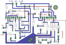
Also, I've made a PCB, so I was wondering if anyone can check it out and see if it's alright (note: the red lines are jumper wires).
Thanks for your help and time!")
I'm building a tube preamp, the "AX84 Clean Preamp" to be exact, and I'm unsure what voltages does B+ need to be for powering the tubes. I plan on using Electro-Harmonix (12AU7 and 12AT7).
The voltages are marked as B+4 and B+5, so I suppose they have to be different.
Also, I've made a PCB, so I was wondering if anyone can check it out and see if it's alright (note: the red lines are jumper wires).
Thanks for your help and time!
Attachments
There are lots of "gotchas" when laying out tube circuits. Your board may work, it may not. Hum and oscillation are problems for improper layout. The AX84 site has a layout for a turret board for that amp. Just print it out and past it to a piece of turret board, drill the holes and set the turrets. As easy as making a PC board, it will guarantee a good result and it will allow easy repair and replacement of parts.
Chris
Chris
If you look in the schematics for one of the power amplifiers you will see part of the schematic shows the PSU and how the B+ voltages 1 thru 5 are developed.
What use do you intend to put this preamp to? Normally it would be integral with a musical instrument amplifier of some type and would pick up its supply from there. You are aware it's not a hi-fi amp?
w
What use do you intend to put this preamp to? Normally it would be integral with a musical instrument amplifier of some type and would pick up its supply from there. You are aware it's not a hi-fi amp?
w
@chrish: thanks for the suggestion, I think I'll do that
@wakibaki: ahh, why didn't I think of that? I intend to use it in my guitar amp and connect it to a 65w mosfet poweramp which I have.. Thanks a lot
P.S. I saw in the turret board layout that there's a B- there and it's confusing me a bit. Could you clarify this for me please?
@wakibaki: ahh, why didn't I think of that? I intend to use it in my guitar amp and connect it to a 65w mosfet poweramp which I have.. Thanks a lot
P.S. I saw in the turret board layout that there's a B- there and it's confusing me a bit. Could you clarify this for me please?
Mikasu
Your layout has symbols for the 12AX7 and 12AU7 that are 9 pin's in a straight row. Is this because you plan to use wires to hook up to tube socket's? You could make or find symbols that are round and 9 pin witch would mean that you could mount the socket on the board. Also I think that you could eliminate the jumpers with a little more work. Don't forget that a trace can snake between the legs of a componet if there is enought clearance. What cad software are you using?
Your layout has symbols for the 12AX7 and 12AU7 that are 9 pin's in a straight row. Is this because you plan to use wires to hook up to tube socket's? You could make or find symbols that are round and 9 pin witch would mean that you could mount the socket on the board. Also I think that you could eliminate the jumpers with a little more work. Don't forget that a trace can snake between the legs of a componet if there is enought clearance. What cad software are you using?
Mikasu
Your layout has symbols for the 12AX7 and 12AU7 that are 9 pin's in a straight row. Is this because you plan to use wires to hook up to tube socket's? You could make or find symbols that are round and 9 pin witch would mean that you could mount the socket on the board. Also I think that you could eliminate the jumpers with a little more work. Don't forget that a trace can snake between the legs of a componet if there is enought clearance. What cad software are you using?
Yes, I intend to use wires to hook up the tube sockets. I resorted to this option because if I mounted the tubes on the pcb that would mean it would have to be near the back of the amp and that's not convenient for me, plus the pcb would cost more, because I don't fabricate them myself.
I'm using Eagle Cad.
The AX84 preamp circuit shown above is intended to drive one of the AX84 power amplifiers, which have an input impedance of about 1 meg - in the form of a 'master volume' pot. This preamp will not work successfully if driving a much lower impedance solid-state power amplifier.
- Status
- This old topic is closed. If you want to reopen this topic, contact a moderator using the "Report Post" button.
- Home
- Live Sound
- Instruments and Amps
- AX84 Clean Preamp