I need a buffer for a 7pin project. I want to DC couple it to the previous stage. I see it mentioned here and there, but not that many detailed examples. I cobbled this design together, as I have all the parts. Any real advantage of using a CCS with this buffer? If I do, I'll probably sub a more robust part for the bottom transistor (the NPN as voltage reference, I lifted from someone here - Ian, I think). Anything out of wack here?
Sheldon
Sheldon
Attachments
Being constant current devices themselves, trying to CCS load a pentode is, at best, highly problematic. "Head butting" occurs. IMO, the way to improve on resistive loading of pentode CFs is the installation of a suitable inductor ($$).
You said this is for a 7 pin project. Think about paralleling the sections of an inexpensive 6J6 twin triode, as the CF, in combination with CCS loading. The cathodes are already tied together.")
You said this is for a 7 pin project. Think about paralleling the sections of an inexpensive 6J6 twin triode, as the CF, in combination with CCS loading. The cathodes are already tied together.
Being constant current devices themselves, trying to CCS load a pentode is, at best, highly problematic. "Head butting" occurs. IMO, the way to improve on resistive loading of pentode CFs is the installation of a suitable inductor ($$).
I know you don't want to use a CCS plate load for a pentode, because the plate is isolated from grid1. Therefore the current through the plate won't change much with voltage changes at the plate, meaning the current source would be trying to drive a high impedance.
I don't see the same issue when using a current sink under a pentode follower. Connected at the cathode, the current sink is working into a low impedance. Isn't this the same as for a FET? You wouldn't put a current source to load the drain, but a sink under a follower is pretty common. Is there an analysis of this written up somewhere?
The twin triode is a nice idea, but I already have the 6AU6. Also, I wanted to do a pentode follower, cause I haven't tried one yet.
Sheldon
Last edited:
A 6AU6 is terrific for the CCS (high plate resistance), but its transconductance is too low to make a really good CF.
I should be more specific. I'd be using it to drive a preamp, but not a lot of cable. My current one (DEQX) has 50k input impedance. Would that still be an issue? Or, where would you draw the line for this tube?
Sheldon
50k and small capacitance shouldn't be a big deal. But you know me, always trying to get things optimal...
The real advantage to a pentode CF is lowered input capacitance (yes, there's slightly higher gain, but we're talkin' the difference between 0.92 and 0.97). I've gotten interested in trying them myself (see the SY/Pete Millett crossover thread), so will probably have some distortion spectra for the 6AU6 as a CF in the next week or two.
The real advantage to a pentode CF is lowered input capacitance (yes, there's slightly higher gain, but we're talkin' the difference between 0.92 and 0.97). I've gotten interested in trying them myself (see the SY/Pete Millett crossover thread), so will probably have some distortion spectra for the 6AU6 as a CF in the next week or two.
50k and small capacitance shouldn't be a big deal. But you know me, always trying to get things optimal...
The real advantage to a pentode CF is lowered input capacitance (yes, there's slightly higher gain, but we're talkin' the difference between 0.92 and 0.97). I've gotten interested in trying them myself (see the SY/Pete Millett crossover thread), so will probably have some distortion spectra for the 6AU6 as a CF in the next week or two.
Cool. Thanks,
Sheldon
I've gotten interested in trying them myself (see the SY/Pete Millett crossover thread), so will probably have some distortion spectra for the 6AU6 as a CF in the next week or two.
Ever try it?
Sheldon
I've been thinking a lot lately about using a zener tied to the cathode to bias the screen grid in a number of pentode based applications - you could use a ccs to drive the screen and zener - I have no idea how linear this would prove to be, but is something I am thinking of trying in a very high voltage error amplifier I am working on for my next amplifier project. Might be interesting and if it works reasonably well it would save the cost of a large high quality screen cap.. Just a thought.
Ever try it?
Sheldon
Yes. Not impressed.
The problem is that you really don't get much better performance from it in the context of audio. The capacitances are reduced, which could be significant for an electrometer, but meaningless here. Distortion was low, but source impedance was still 1/gm, so not really any better than a triode. The only other performance advantage (in exchange for a higher parts count) was a slightly higher gain. But if you can hear the difference between a gain of 0.95 and one of 0.98, you're a better man than me.you could use a ccs to drive the screen and zener
Thats the way to go! Use a depletion FET like DN2540 together with a 7-pin gas regulator tube. Then the sand is gone.....
Think you will find it in MJKs latest thread.
Thats the way to go! Use a depletion FET like DN2540 together with a 7-pin gas regulator tube. Then the sand is gone.....
Think you will find it in MJKs latest thread.
Getting the sag and time constant of the screen cap out of the picture is a side benefit, but my main reason is to eliminate screen current variation from the diffamp tail current in this pentode driver loaded by V/I feedback:
http://www.diyaudio.com/forums/tubes-valves/163940-g1-g2-mu-scaled-drive-strawman-design.html
Michael
PS now this is interesting: "The place where this does make sense is in a VCVS based filter in a line level X-O... "
or maybe using remote cutoff pentodes in a "vari-mu" compressor circuit...
Last edited:
Distortion was low, but source impedance was still 1/gm, so not really any better than a triode. The only other performance advantage (in exchange for a higher parts count) was a slightly higher gain. But if you can hear the difference between a gain of 0.95 and one of 0.98, you're a better man than me.
Thanks. May still try it just for something a little different. And I got the parts. But maybe 6JC6 instead of 6AU6.
I've been thinking a lot lately about using a zener tied to the cathode to bias the screen grid in a number of pentode based applications - you could use a ccs to drive the screen and zener - I have no idea how linear this would prove to be. Might be interesting and if it works reasonably well it would save the cost of a large high quality screen cap.. Just a thought.
With a reasonably quiet supply, wouldn't a resistor do almost as well as a ccs, especially with a ccs on the cathode?
Brings up another question that puzzles me. I would think that the impedance of g2 should be paralleled with the dropping resistor, to calculate the cap to cathode. But I'm a bit mystified as to how to calculate, or even estimate that. Data sheets don't show grid curves with other factors held constant. I'm thinking that it would typically be relatively high with a current source on the cathode, as a voltage change at g2 could only change current at g2, in opposition to current at the plate.
Sheldon
Been thinking about the follower, and came to the conclusion that a mu follower would be the better choice for my project. Here's what I'm planning on using it for, and three different versions of the mu follower. I'm thinking that at the low currents I'm running, the SK170 might be the better option as the controlling device. Or?
BTW, phono amp is from Dmitry Nizhegorodov. Shunt supply a version of Salas's supply.
BTW, phono amp is from Dmitry Nizhegorodov. Shunt supply a version of Salas's supply.
Attachments
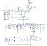
Right now, I'm thinking that the gyrator mu follower will be a nice fit. If I use the cascoded version, I'm also thinking it would good to bias up the top device some with a battery. Of course, an enhancement mode device on top would need to be biased. But even with the depletion mode device for the top, some extra voltage across the lower device might be desirable. Without additional bias, the DN2540 would only put about 2V across the SK170.
Sheldon
Sheldon
Right now, I'm thinking that the gyrator mu follower will be a nice fit. If I use the cascoded version, I'm also thinking it would good to bias up the top device some with a battery. Of course, an enhancement mode device on top would need to be biased. But even with the depletion mode device for the top, some extra voltage across the lower device might be desirable. Without additional bias, the DN2540 would only put about 2V across the SK170.
Sheldon
An IXYS 01N100 or 10M45 would drop -3V Vgs at low current, which is probably OK for a 2SK170 bottom device in a cascode. Based on the 2SK170 datasheet the Ciss would be about 33pf at 3Vds and would only decrease to 30pF if Vds is increased to 10V.
I'm thinking about a cascode gyrator using a 2N7000 + 01N100 myself, but the 2SK170 is a great choice for lower current operation and the 01N100 will work fine at a couple of mA.
Cheers,
Michael
PS for a single device you might consider the FQP2N60C at about 4pF Crss and 20pF Coss
Last edited:
Thanks Michael. I was thinking not so much the Ciss as getting on the flatter part of the curve, but 3V looks pretty good there if the data sheet is accurate. Don't know if that matters much here. The 10M45S does look like a better fit than the DN2540, and I have a couple. I'm liking the gyrator idea, as I can set the voltage so that tube drift will be less of an issue. Plus, the voltage from the input supply is just right for the output tube.
Also, since this is the output tube for the preamp, it's a good spot for a slow start circuit for charging the output cap. I've use simple RC circuits to delay power for other projects, and Greg (Geek) mentioned the application for the gyrator. It should flatten any power on thump. Alas, I suspect that I'll still get some thump on power off, as there is little storage in the HV supply.
Sheldon
Last edited:
EF184 looks like a nice tube. I actually got some 6JC6 for cheap. Very similar specs. But I think for this project, the mu follower makes sense. I need one less HV regulator, and the voltages work out nicely. I had thought about using a tube for the mu CCS or gyrator, but don't I don't think I have enough voltage to make that work well(could make the supply a cap input supply). More important, maybe, is that the current is pretty low to feed the output tube plate, in this configuration. That's why the sand based gyrator seems most practical.
Sheldon
Sheldon
- Status
- This old topic is closed. If you want to reopen this topic, contact a moderator using the "Report Post" button.
- Home
- Amplifiers
- Tubes / Valves
- pentode buffer