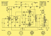
The FB signal applied to the voltage amplifier cathode must be in phase with the signal applied to the voltage amplifier grid. If the signal at the 8 Ω speaker tap of the O/P trafo is out of phase with the I/P signal, exchange either the O/P trafo primary wires or the lines coming from the phase splitter, but not both.
Sorry, hope this is not too off topic, regarding a decent test tone generator, a cheap one can be had with this kit Altronics - Your One Stop Audio Visual & Electronics Supplier it is based on the design by Rod Elliot of Elliot Sound Products (I use his active crossover boards) Miniature Audio Oscillator
Altronics is an Australian electronics kit/parts distributor so don't know if they ship overseas. I have two of these, they are very cheap and produce a nice clean square wave and sine wave. The claimed output of 41Hz-18kHz was designed to stop speaker damage and can be changed with a few minor component changes.
Regarding the feedback, I use the dumb method. Wire it up leaving the feedback disconnected at one end. On the disconnected end, use a wire with alligator clips or similar. With the scope connected to the output and a signal at the input, connect the feedback circuit with the alligator clip. If the amplitude increases, your feedback is positive, if the amplitude decreases, the feedback is negative. If the feedback is negative, all is OK. If it is positive feedback, correct using the method Eli describes above.
Good luck with the project!
Chris
Salas, Attached is the original Mullard 5-20 diagram. I think it is a matter of symantics as to how it is drawn in this case as long as they are in phase. I put a signal generator symbol with a positive wave form to indicate phase on the input and output.
I have come to the conclusion that my second channel on the osc scope is messed up worse than originally thought. Now I am not sure if I have the signal in phase or not. I ran a test signal through both channels, one instant they are in phase the next they are not. Thought I was seeing things so asked the wife to look and she said they looked the same???????? Oh Well. Good excuse to go to ebay, have a "new to me" scope coming next week, a Tek 2430A. I think that will do well for most analog stuff.
I am going to assume that I had it hooked up for positive feedback since when I lower the feedback resistor value, the gain increases.
To get NFB working, I need to identify where I am losing stability, something still is not quite right on the amp in regard to phasing and noise. With a 100k resistor for feedback hooked the other direction it can't even power it up without oscillating. (I don't feel like losing tubes)
My plans are to
1) Clean up my mess (Wife's Orders)
2) Install ferrite tomorrow
3) Install 2SK3563's instead of IRFBC20
4) Install "Wire Wound" anode load resistors for the LTP. MOX that are in now are VERY noisy.
5) Test each stage for gain, phase, and distortion.
6) Fix any problems and then try NFB again with certainty of phase.
Attachments

Looks like you may have been typing while I was answering. The empirical method to determine feedback mentioned above only needs one channel of the scope and you don't have to think about phase.
On the other hand, if you need an excuse to justify to SWMBO the purchase of a new toy, I will play along")
Cheers!
Chris
On the other hand, if you need an excuse to justify to SWMBO the purchase of a new toy, I will play along
Cheers!
Chris
My plans are to
1) Clean up my mess (Wife's Orders)
2) Install ferrite tomorrow
3) Install 2SK3563's instead of IRFBC20
4) Install "Wire Wound" anode load resistors for the LTP. MOX that are in now are VERY noisy.
5) Test each stage for gain, phase, and distortion.
6) Fix any problems and then try NFB again with certainty of phase.
Wow. It's almost the same as my list. Only the last 5 items are different.
..Todd
Unless your transformer winder specifies the absolute polarity it is not safe to assume that yours match the schematic even if the colors are the same. In the SE world I find about a 50 -50 mix of "normal" and "inverted" polarity on OPT's. So far every Edcor that I have seen inverts and most Hammonds do not. My Electra - Prints are in a no feedback amp, so I dont know the absolute polarity. I wire the speaker leads up so the speaker cones move out when the bass drum gets stomped. Determined to sound correct when my daughter lived at home and played the drums. We made a lot of live recordings then. I think half of the high school marching band lived here then. The neighbors thought so.
I haven't seen a large enough sample size of P-P OPT's to get the trend, but If you look at the documentation for Pete Milletts engineers amp you will see that his pictures do not match his schematic. It would appear that the Edcor P-P's also invert the polarity.
I haven't seen a large enough sample size of P-P OPT's to get the trend, but If you look at the documentation for Pete Milletts engineers amp you will see that his pictures do not match his schematic. It would appear that the Edcor P-P's also invert the polarity.

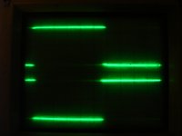
Proof. I wasn't crazy
It wasn't my eyes playing tricks....My scope isn't doing too well.
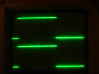
Attached photos are of both channels hooked to the calibration rail. The first photo shows them out of phase. The second shows it in phase. Didn't touch anything.
Even though it probably has to do with the trigger, channel two won't calibrate correctly with 10x or 100x probes. Have to wiggle the sensitivity selector to display the signal.
Showed it to my wife and she agreed that I need a new scope. I love my wife.
Chrish keep your mouth quite! You to Salas.... Nice clip
It wasn't my eyes playing tricks....My scope isn't doing too well.
Attached photos are of both channels hooked to the calibration rail. The first photo shows them out of phase. The second shows it in phase. Didn't touch anything.
Even though it probably has to do with the trigger, channel two won't calibrate correctly with 10x or 100x probes. Have to wiggle the sensitivity selector to display the signal.
Showed it to my wife and she agreed that I need a new scope. I love my wife.
Chrish keep your mouth quite! You to Salas.... Nice clip
Attachments

It wasn't my eyes playing tricks....My scope isn't doing too well.
Attached photos are of both channels hooked to the calibration rail. The first photo shows them out of phase. The second shows it in phase. Didn't touch anything.
Even though it probably has to do with the trigger, channel two won't calibrate correctly with 10x or 100x probes. Have to wiggle the sensitivity selector to display the signal.
Showed it to my wife and she agreed that I need a new scope. I love my wife.
Chrish keep your mouth quite! You to Salas.... Nice clip
My old Tek scope is getting long in the tooth too! Switches, and knobs are acting funky also. I don't like working on test equipment, so I found some good values on NEW (in Calibration scopes). Got a BK 30Mhz analog, and a Rigol 100Mhz DSO. Very happy with what I got for the $$$$$$$$. No more futzing!
Tubemack,
How do you like the Rigol. I saw that and it may be what I am looking for for a distortion analyser seeing that it has FFT. Certainly the price is right, particularly for a hobby. The PC Soundcard has its advantages but it doesn't help me with the high frequency oscillations I am having now.
I also picked up a BK 20MHz analog for $50.
I like the Rigol for the price. The 100Mhz version was around $700. Rigol makes the Aligent base model DSO's, so they aren't too shabby. The FFT function is only 8 bit as with all Dso's ( short of Multi thousand dollar units). You will need a DA to kill the fundamental for increased resolution. I use a HP 339a. The prices on these seemed to have bottomed out on Ebay recently.
Last edited:
I didn't know the HP339a had a notch filter.
Any THD meter that doesn't work by FFT uses a notch filter. The analyzer works my measuring the input signal level, then notching out the fundamental tone, measuring what's left, and comparing the two numbers. Most of the old HP stuff has the notch filter output available. I have two 331A's. Using one of them you can extend the range of the 8903A (not really needed for tube amps) or notch out the fundamental and send the residual to your sound card for analysis. You can daisy chain two of them for IMD measurements. The 331A is a totally manual meter that is not exactly user friendly, but I got them 25 years ago for $25 each. Back then they were the only affordable choice.
- Status
- This old topic is closed. If you want to reopen this topic, contact a moderator using the "Report Post" button.
- Home
- Amplifiers
- Tubes / Valves
- OPUS 5.0 A Modern Mullard