Decided on SiC Schottky. Left snubber caps in for now, I don't think it would hurt.
TOTALLY unnecessary! Being majority carrier only devices, Schottky diodes do not exhibit a reverse recovery spike.
OK. All parts that can be pretty much pinned down have been ordered.
The rest of the parts should be in my parts bin(s).
Now I just need to finalize the iron and address any comments, suggestions, or errors in design based on your input(s).
I figure I can do alot more reading, studying, and analysis. I beleive that the school of solder and measurement is where I am going to learn the most.
FYI. I will not use the big caps during the initial construction and proof testing. Even with lineman gloves, there is too much risk to be prodding and probing during the inital breadboard phase.
Thanks for everyones help so far. Especially Eli's
FYI. I will not use the big caps during the initial construction and proof testing.
I have some 2400 uF 450 volt monster caps. They may not be in the same league as yours, but I was unimpressed with them. I needed some big caps to put in series for my 845SE amp, so I got those. I ran 4 of them in series in an 1100 volt supply. Talk about big, and serious energy storage too. The deal buster came when I could see several volts of ripple across them when the amp was driven to clipping with a 5KHz square wave. Some "small" 220 uF 450 volt Panasonic snap in's worked much better even though they were less than 1/10 the value. I added a 4 uF 2000 volt oil cap in the amp chassis right at the red wires of the OPT, and I couldn't see anything on the B+. I am guessing that the ESL (inductance) of these caps is high enough so that they work well at 60 Hz, but suck at 5KHz and higher.
Further experiments with these caps and a Simple SE led me to realize that a film based motor run cap worked far better, so the big electrolytics are in the closet, and likely will get voted off the next time I do a clean up of the closet.
Thought I would put the latest schematics up for the amp and power supply as it sits now.
I should also than George at tubelab for sharing his power drive
George, you may be right in the big caps. I guess it will be interesting to see what these do. If I don't try I will always have these things in the back of my mind bothering me..... I will run the experiment
I should also than George at tubelab for sharing his power drive
George, you may be right in the big caps. I guess it will be interesting to see what these do. If I don't try I will always have these things in the back of my mind bothering me..... I will run the experiment
Attachments
Last edited:
Thought I would put the latest schematics up for the amp and power supply as it sits now.
Its hard to keep up with all of the KT88 P-P threads. I looked at your schematics and noticed one thing. Your negative power supply is -90 volts. In my KT88 test amp I needed to increase my negative supply to -105 volts when cranking KT88's hard in triode mode. I was using resistors in the source leads of the mosfets. The 10M45 needs about 20 volts across it to be happy. You may need a bit more than 90 volts in your case.
Also putting the entire B+ on the drain of the mosfet makes it rather warm but it wont be a problem with a good heat sink. I use a rather low +25 volt supply during my testing, since one of the power supplies on my bench only goes to 25 volts. Another very valid reason is that if a mosfet ever decides to short out it will put the full B+ on the grid of your KT88. This will make them very unhappy, and I think you are planning to use some rather expensive tubes.
What are you planning to use for your power transformer?
I built an experimental amplifier that made 75 Watts in triode mode using EH KT88's. That design was detailed from the paper napkin scratchings up to a working prototype. Ignore the title of the thread. It might be interesting reading if you have a few hours to burn.
http://www.diyaudio.com/forums/tubes-valves/133034-6l6gc-ab2-amp.html
I looked at your schematics and noticed one thing. Your negative power supply is -90 volts. In my KT88 test amp I needed to increase my negative supply to -105 volts when cranking KT88's hard in triode mode. I was using resistors in the source leads of the mosfets. The 10M45 needs about 20 volts across it to be happy. You may need a bit more than 90 volts in your case.
Scott,
IMO, you should heed the voice of experience. With that in mind, I suggest you phase up the 75 V. and 5 V. windings, wire them in series, and rectify the composite. R102 becomes a simple bleeder, not a voltage set part. George has made clear that too few Volts is the issue with 10M45Ses, not too many. Insert a RC decoupling network between the point the B- (FETs/CCSes) is taken and the point C- (bias) is taken. Given the bias set trim pots., I don't think that any particular "locked" value for the C- voltage is necessary.
George,
Thank You for your comments. Very Good Points.
Power Tranny will be either a Edcor or electraprint. Jack is working on quoting my choke and OPT's right now. I havn't ordered the PT yet as I am waiting on some feedback like yours.
Your point is well taken on negative bias, easy enough to change at this point. I can spec 85V on the bias winding and hit 105V. I was thinking about what would happen if the CCS or the FET fails. Certainly tube failure is one real possibility. Another one is what happened on the tubelab SE. When a FET failed, (I didn't tighten my heatsink well enough), it took out a bias rectifier and blew the power fuse. (I won't count on that to happen).
I will have to think about adding more to the PS to give an intermediate voltage to tie the FETS to. It is already getting complex. I calculate about 6W dissapation for each which is easily handled with the heatsink I was planning to use. Something to ponder......
I started reading that thread a few days ago and haven't got to the point of you needing to drop the rail. I'll keep reading.
Non of the kt88 tubes are cheap!!!! For testing and initial proofing, I will use the cheaper EH.
Eli, I am all ears on this stuff. Not sure what you are saying. Let me see if I understand, put a R and C in parallel to each other between B+ and the drain of the FET?
Nope re read what you were saying and am not shure what you mean.
Last edited:
TOTALLY unnecessary! Being majority carrier only devices, Schottky diodes do not exhibit a reverse recovery spike.
But they exhibit higher capacitance than conventional diodes, and it's internal capacitance and parasitic circuit and package inductance what produces RF ringing (LC tank resonator, which needs external RLC with custom values for optimum damping).
btw: A complete waste to use a SiC diode in place of a 1N4007. Some of us are actually doing commercial switching power electronics and we think twice before using SiC due to the high cost... In places where it really improves performance... And the MBR40250... I use them in the power supply of an amplifier capable of 10kw peak, so it's funny to see it in a 20mA supply

Last edited:
Latest based on Eli and George
Eli, here is my interpretation of what you said. I didn't put any values yet as it is getting close to bedtime.
George, -bias has been increased. If it still is not enough, I can easily series the 5V to the bias winding an gain a few more volts as Eli suggested
Thanks Again
Eli, here is my interpretation of what you said. I didn't put any values yet as it is getting close to bedtime.
George, -bias has been increased. If it still is not enough, I can easily series the 5V to the bias winding an gain a few more volts as Eli suggested
Thanks Again
Attachments
Based on Tubelabs comments I drew up this version for peer review and consideration.
I added a 25V rail which at least at this time is regulated with a LM317 set-up for high ripple rejection. I also added a resistor to tie the wiper of the bias pot to the C- should it open up. I am thinking that the impedance of the bias circuit is too high as it stands and may be subject to noise pick-up.
This design does drop the power dissapation of the FET down considerably. (approx 1.2W). The complexity of the power supply increases significantly with the potential of adding more hash into the HT rail due to the addition of another rectification bridge. (It will be schottky)
Bear with my thinking for a moment. In this case if the FET fails it would send the Vg to 25V which would also cause a tube melt down if not caught quick enough. The question I pose is: Is the added complexity worth the benefits? While reducing the demands of the FET, it adds potential other failure modes.
Is there a more eloquent solution in this topology?
Attachments
I started reading that thread a few days ago and haven't got to the point of you needing to drop the rail. I'll keep reading
I haven't read my own thread in a while, but I believe that we always planned for a pair of rails in the + - 100 to 125 volt range. The method for acheiving this may vary. This is based on my experience with the Tubelab SE amp where the fet runs on the B+ supply. I have had no issues running the Tubelab SE on supplies from 300 to 360 volts or so. A few users have seen fried fets from running their amps in the 400 volt range, and I have set a mosfet on fire and burned up the bias supply by running 480 volts on a board using sweep tubes. There is just too much dissipation in too small of a space.
Based on Tubelabs comments I drew up this version for peer review and consideration.......Is there a more eloquent solution in this topology?
I'll tell you what I have been doing. I use a seperate transformer just for cost reasons, but if you are going custom consider this. You need one winding of 160 to 240 volts CENTER TAPPED. Ground the CT and use the typical 4 diode full wave bridge (as found in most SS amps) to generate + - 125 to 150 volts. In my designs I use the Triad N-68X isolation transformer ($11.20 at Mouser). I use the 120 volt "secondary" as the primary, and series the two "primaries" to make a 240 VCT secondary. Filter and / or regulate these supplies as you see fit to arrive at the required voltages. I picked +25 volts for my bench testing because that is the max my bench supply will put out. Many of my test amps have been using + - 150 volts directly from the CLC filtered bridge output.
Top Secret tip!!!! When you make a symmetrical (+- same voltage) supply like this, with almost identical load currents, use a "common mode" choke. This type of choke has two windings, one winding is used in each supply, so that the hum exactly cancels out. You can buy a good one like the One Electron RC-2 ($70 at AES) or you can cheap out and use an isolation (two 120 volt windings) transformer as a choke (this only works where the DC currents are equal).
In this case if the FET fails it would send the Vg to 25V which would also cause a tube melt down if not caught quick enough.
+25 will cause a serious current flow through the KT88. +450 or so will cause an instantaneous G1 to cathode arc (proven on a 6L6GC). +150 is in the "I really don't know what will happen" range. I have not had a failure yet. It is a good idea to add a small 125 mA or so fuse in the cathode circuit of each KT88.
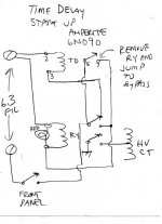
boywonder, I am interested in the delay setup.
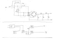
Here you go. These are both from other threads/members here. I've breadboarded the second one and it works fine (upper schematic). Disregard the lower schema on the second image. I would go with a 45 sec-1 minute amperite time delay relay to allow the heaters to get toasty before applying B+.
When the TDR closes, it energizes the second relay which powers up B+ and takes the TDR out of the circuit to cool for the next power cycle, so even quick power cycles will have a start-up delay.
Of course this adds a little complexity to the PS but the amperites look pretty cool......
Attachments
With a common mode choke, Wouldn't the impedance pretty much cancel each other out at the lower frequencies? I asked Electra-print to quote me one and he said a "Common Mode Choke" would only work in the Mhz range. Great for RF but not for ripple.
In my mind I can make it work, but I am confused with his response.
Of course in my mind I can fly without an airplane!!!!!
In my mind I can make it work, but I am confused with his response.
Of course in my mind I can fly without an airplane!!!!!
Last edited:
Output Iron Ordered: Electraprint 4.3K Zp-p Primary @ 6ohm Secondary. 100W 40% UL tap.
Now to tweek PT.
There is alot of good advise here in regard to setting up the rails for the FET. After considering what the FET failure risks are versus the amount of complexity needed to at least mitigate the risk, I am leaning towards letting the tube arc but protecting the OPT. If I was to place a 300mA fuse between the B+ and the OPT, it should acheive that goal. In regard to the FET, I sourced a 900V 2sk2700 equiv (2SK3564) that has 900V Vds capability. It still has a low reverse transfer capacitiance but has 400V more capability than the 2sk3563. Power dissipation aside, this will at least handle start-up voltages.
If FET heat is a problem even with the heat sinks planned, then it should be easy enough to install a small xfmr under the deck to provide 25 or more volts to the drains of the FET. This will minimize the concern of hash on the main core.
What do you think?
boywonder, thanks.
Last edited:
Does using FETs for coupling negate the need to keep the bias resistance below 100K for >35W output according to the KT88 data sheet?
The output resistance of the fet is on the order of a few ohms, and the impedance of the fet's power supply better be low, so the requirements are satisfied.
With a common mode choke, Wouldn't the impedance pretty much cancel each other out at the lower frequencies? I asked Electra-print to quote me one and he said a "Common Mode Choke" would only work in the Mhz range. Great for RF but not for ripple.
It is not uncommon for someone to resist new ideas. I respect Jacks transformer winding, and I have a pair of his OPT's in my Tubelab SE with 45 tubes. That is the best sounding amp that I have ever built and it has whupped some rather expensive amps when played next to them through Lowthers. Jack told me that PowerDrive, and using silicon to drive big DHT's was stupid. Have you seen some of his new schematics that use a chip amp to drive a DHT through an Electra-Print transformer?
The common mode power supply choke is not even a new idea. In fact I saw it mentioned just a few days ago in a thread on the Tubelab forum. Look at the application notes on good power supply design at the bottom of the page.
5U4G Data sheet. Emission Labs.
In my mind I can make it work, but I am confused with his response. Of course in my mind I can fly without an airplane!!!!!
Flying without an airplane is possible, in fact I watched some competitors fly a snowboard just last week!
- Status
- This old topic is closed. If you want to reopen this topic, contact a moderator using the "Report Post" button.
- Home
- Amplifiers
- Tubes / Valves
- OPUS 5.0 A Modern Mullard