capacitance.
Hi Scott
Answer a tubie newbie question for me.
This might seem like a daft question looking at your power supply.
Obviously in SS there's no such thing as too much capacitance.
But in tubes is it possible to use too much and have problems at switch on with damaged plates or filaments.
Have tried to look into this today but can't find the answer.
I see you have two switches to let heaters warm before HT goes on.
Are the motor runs on the lower voltage pre tubes, and the biguns on the main HT ?
And what caps have you got on your heaters.
I should go to bed and stop thinking about amplifiers !!!
Simon...

Its a mix.
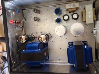
Actually there is a surge surpressor prior to the HV schotkey diodes. In this case the diodes are plenty big enough, but the PT will complaign. For tube rectifiction there is a limit on the size of the initial capacitor depending on its construction. That information is spelled out in the tube datasheet for each one. The problem is not only during start-up but mainly during normal operation. A tube rectifier does a nice job of self current limiting itself up to a point while it warms up.
The filament switch is to warm the filaments of the amplification tubes prior to B+. It is suppose to stop cathode stripping. I really don't use it much. Personally, I just flip them on simutaneously most of the time. I am sure both sides of the cathode stripping camp will have something to say here so flame on. The red and black switch does look good though ;-)
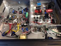
As for the motor runs, they are used throughout the PS. They are the initial capacitor prior to the choke, a bypass cap for the big honkers, a resivour for the LTP and finally a resivour for the input tube.
For the heater caps, those are axial mkp but in truth, ceramic will do much better and be more compact in this application. It would be best to have those tie direct to the metal socket mounting ring for ground instead of away as they are built. I got them by accident and at a bargain so I kept them.
Sleep Tight.
Actually there is a surge surpressor prior to the HV schotkey diodes. In this case the diodes are plenty big enough, but the PT will complaign. For tube rectifiction there is a limit on the size of the initial capacitor depending on its construction. That information is spelled out in the tube datasheet for each one. The problem is not only during start-up but mainly during normal operation. A tube rectifier does a nice job of self current limiting itself up to a point while it warms up.
The filament switch is to warm the filaments of the amplification tubes prior to B+. It is suppose to stop cathode stripping. I really don't use it much. Personally, I just flip them on simutaneously most of the time. I am sure both sides of the cathode stripping camp will have something to say here so flame on.
The red and black switch does look good though ;-)As for the motor runs, they are used throughout the PS. They are the initial capacitor prior to the choke, a bypass cap for the big honkers, a resivour for the LTP and finally a resivour for the input tube.
For the heater caps, those are axial mkp but in truth, ceramic will do much better and be more compact in this application. It would be best to have those tie direct to the metal socket mounting ring for ground instead of away as they are built. I got them by accident and at a bargain so I kept them.
Sleep Tight.
I'm slowly building up sub-assemblies for a mutation of this build and I have a question about the B+ and C- rails. I'm building a stereo chassis and I have the option of using separate B+ and C- rails for each channel or having the channels share rails. Any disadvantage to sharing the rails? It would save space, diodes & caps, but I'm OK with leaving them separated.
Another Opus 5.0
I think I am close to completing SGregory's "Opus 5.0". I say I think I'm close because another problem has shown itself, as soon as I input a signal there is a high frequency buzz, almost a whistle, coming from the output transformer. I have the oscilloscope connected across the speaker terminals with an 8 ohm load attached. The signal generator is connected to the amps input rca and a 2.5kHz 1.414Vpp signal applied. I have only left it for a second because of the buzz. Output tube bias is set at 0.45V and all other voltages are where they should be.
As I was writing I remembered about a month ago I had the amp connected briefly to speakers and played music with it connected to my phone. I noticed no transformer noise then. That's the problem with DIY, when IQ have to take a break to work it takes a while to remember where I was. I am going to go over it again and check any changes I've made since then.
If anyone has experienced anything similar please let me know.
Attachments
Ok, I thought it was coming from the output transformer then I thought the power transformer ( I work in the garage and the air handler is not far away, difficult to hear ), finally the AC shut off and I am sure the sound is from the output side of the chassis and this time I had the meters set up to monitor bias voltage and when I applied the signal, bias voltage more than doubled quickly. I have never input the signal longer than a second or 2.
I have a 1kR resistor and ferrite beads at g1 of the output tube and ferrite beads on the gate to the fet.
I have a 1kR resistor and ferrite beads at g1 of the output tube and ferrite beads on the gate to the fet.
This is the first time I have come across this project before. SGregory do you happen to have a final schematic of the PS that accompanies the final schematic for the amplifier? I'm also curious if you think it would be a worthwhile addition to convert the output tube bias to LED bias a la the RLD amplifier.
- Status
- This old topic is closed. If you want to reopen this topic, contact a moderator using the "Report Post" button.
- Home
- Amplifiers
- Tubes / Valves
- OPUS 5.0 A Modern Mullard