I am having a very difficult time understanding how a triode fed (for that matter a pentode fed) LTP circuit works with respect to input signal.
In this case the triode is current source loaded and the LTP has a CCS in the tail. The LTP is a 12at7. To me, it would seem that the LTP can take a direct signal from the source without the need for amplification as the Vg will be around +1V.
In a mullard 5-20 configuration, (as in the recent thread(s)) the LTP is driven by a pentode or triode with a pretty high gain. (it also has 30db feedback so I understand why some gain is required to overcome that.)
In my pea brain, I think the answer lies in the behaivor of the ltp with the cathode potential moving with current. I can't get my thoughts around how the cathode potential moves to accomodate such a large signal from the driver.
Is there an easy explanation that a material engineer can understand?
Thanks
The current source in the triode drive circuit acts as a near infinite load impedance allowing the full Mu of the triode to be utilized for voltage gain. So you have a lot of voltage gain available.
I think of a LTP (particularly with a current source in the cathode) as a sea-saw. Since the cathode current source provides a fixed current to both tubes (fulcrum), if one draws more, there is less left for the other. This results in the LTP not seeing it's cathode swing as much as one would expect.
With a grid drive requirement of about 30V, the EL34 does not put an extreme requirement on the LTP. If the LTP had a gain equal to mu, it would only need 30/19.7 = 1.523V swing at the grid to drive the output to clipping. The cathode of the LTP does swing since one grid is tied to ground, but it only swings through this 1.523V requirement.
If the gain of the LTP (12AU7) is 19.5, and the gain of the input triode (12AX7) is 100, then you have one boatload of gain to drive the EL34s. Open loop the input requirement is only 30/100/19.5 = 15.4mV. Obviously GNFB reduces the input sensitivity and it will take a considerably larger input signal.
In addition, the gains will not be the full X100 and X19.5 so this also will result in more input dive.
Last edited:
Wow, thanks Gimp! Very useful post. I am working on a similar idea in an EL34 PP rebuild.
I am planning to use 1/2 6sl7 without cathode bypass into a 6sn7 LPT with a CCS, but am concerned that it just will have too much gain, unless I want to swat it down with loads of feedback.
My source is a 2Vrms DAC (Red Wine)😀
Could I just skip the 6sl7 and input directly into the LPT?
I will post more regarding this at a later date when I have a schematic and can ask the forum helpfuls like yourself for reassurance and advice (I will have a lot more q's), but i am not quite ready yet.😱
My source is a 2Vrms DAC (Red Wine)😀
Could I just skip the 6sl7 and input directly into the LPT?
LTP has ~1/2 the voltage amplification of straight common cathode stage which in case of tube with mu = 20 is 20x at best, and likely to be lower. This might just be enough with 2V RMS input (~25V P-t-P swing at the grid of EL34), depending on how you intend to operate your EL34s.
Well, since I abm rebuilding the entire front end of this amp (it was using a 6u8 in pentode input, triode concerta) /i can work out the bias as I wish.
I see options based on what tubes I have.
1. use the 6sn7 as the input mu 20 and the 6sl7 as the LPT (problem, I only have one 6sl7)
2.6688 (E180F) input mu 50
3. 6cg7 input mu 20
4. 6u8 input mu 40
Any thoughts on what might be worthwhile out of this gamish? I am kind of saving the e180f's for a 300b design....
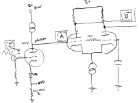
Here is what I am talking about.
In the attached schematic (I am sure it is missing a few grid stoppers) lets assume the input triode has a mu of 50. Without feed back a +/- 1V input will result in +/- 50V output at the anode [A]. (Theoretical ). How does the LTP eat this voltage without clipping? Or do I have to have enough NFB to drop the gain so that the triode output [A] is within the limits of the input grid on the LTP.
For this example lets assume the LTP is a 12at7 running at 460V and 3mA per side. Anode resistor is 50k. The gain in the LTP would be somewhere around 27dB assuming it is lightly loaded.
Please ignore that I wrote mu=100 on the drawing. Not close enough to the real world.
Attachments
Since you are DC coupling, I believe the grid of the non-inverting half of the LTP needs to be at the same DC potential as the input tube's anode, approximately, but with none of the AC signal. Connect 1-2 Meg from first LTP grid to second LTP grid. Alternately, a fixed voltage source could be used for better fidelity but with more adjustment requirements. There always needs to be a DC path to ground from the grids. Obviously the cathode voltage of the LTP will need to be higher than the anode voltage of the preceding stage, by exactly the intended Vgk bias for the LTP.
In terms of clipping, any voltage higher than the difference between cathode of LTP and anode of first stage will force grid current. No coupling cap will allow this to occur, however it will distort the up-going cycle of a sine wave by "rounding" it out. Ideally, the peak to peak voltage input of the LTP should be no more than 2*vgk, with LTP center biased.
If you have a PC, or linux machine go and get LTSpice, it's free and easy, and lets you test the circuit (approximately) before you build it. The learning curve isn't too terrible if you can already draw a schematic & google error messages.
Last edited:
Another idea is to use a local feedback resistor around the first voltage gain stage to drop its output down to the desired level, as well as increasing bandwidth and decreasing distortion before clipping. It will respond "quicker" than a big gNFB loop.
There is a 1M resistor in the drawing between grids.
If I understand correctly, (unless I want a positive grid potential) the maximum LTP input level posible without distortion is the bias voltage. Or Vp-p = 2x bias. (Assuming grid current doesn't start sooner). In the example above, I need to burn the extra gain with NFB (taken from some point further down the chain) to get it within range.
If I understand correctly, (unless I want a positive grid potential) the maximum LTP input level posible without distortion is the bias voltage. Or Vp-p = 2x bias. (Assuming grid current doesn't start sooner). In the example above, I need to burn the extra gain with NFB (taken from some point further down the chain) to get it within range.
Another idea is to use a local feedback resistor around the first voltage gain stage to drop its output down to the desired level, as well as increasing bandwidth and decreasing distortion before clipping. It will respond "quicker" than a big gNFB loop.
I like this idea, given my issue with too much gain at the input.
This would be a resistor from the cathode of the input tube to the grid, right? Making a local current feedback loop.
I have seen this where the Rf come off the cathode between two cathode resistors and the feedback is adjusted by changing the value of the lower resistor (to ground), but this also alters the bias of the tube.
Could one take the Rf off the wiper of a pot so the cathode bias is stable and the feedback is adjustable?
If you don't want global feedback, you probably don't even need/want the first stage. Just use an LTP as the input stage and you're done; with the usual suspects for output tubes, a 12AT7 will drive them to clipping with 2V or so input.
SY is correct, you'll have plenty of gain without an input tube. If you were dead set on having more gain for whatever reason (i.e. 100mV or less source), the local feedback would produce a higher input impedance & wider bandwidth.
I always saw local feedback done like this:
http://www.freewebs.com/valvewizard/localfeedback.html
with resistor from output to input (voltage feedback). I am not sure if you can just lose the cap and DC-couple the feedback. It'd require some figurin'.
If you are planning on wrapping a ton of NFB around this thing, add the voltage stage, but certainly try it first without. An amp set up well for gNFB should sound great already before the NFB goes in, generally.
SY thanks,
My question arose from the KT88 UL thread and reading Mullards material. My confusion (very easy for me to be) arose in the discussion of input tubes and insuring sufficient gain. Others chimed in about not using NFB in the circuit. I thought I was severly missing some concept on how to drive the LTP. I was thinking how the LTP would behave without the GNFB and having the input tube with high mu.
I do intend to run GNFB per the mullard design into the input tube so I will need gain there.
Would you please check the following logic to see if I have this correct.
If the input tube is a 6GK5 mu=51 at 6mA. (assuming 105V plate). With a CCS anode load, and a 2Vpp input signal, I should see a 102Vpp output swing at the plate. Amplification would be 51(or close) or 34dB. With my LTP set up with 470V plate and 50k anode loads with a ccs tail, I could use an input swing of 2.63Vpp.
Assuming I have a 2Vpp signal to amplify I would need 20log(2.63/2) dB or 2.3dB of gain to drive it to full swing.
I would then need (34-2.3) or 31.7dB of feedback for this particular input tube.
Is the above correct?
I would like the GNFB for dampening factor more than distortion control. Your point is well heard that the amp should sound good without it.
I may also use the ef86 in wired for triode. Input tube selection is still open
Thanks
Scott
Last edited:
SY thanks,
My question arose from the KT88 UL thread and reading Mullards material. My confusion (very easy for me to be) arose in the discussion of input tubes and insuring sufficient gain. Others chimed in about not using NFB in the circuit. I thought I was severly missing some concept on how to drive the LTP. I was thinking how the LTP would behave without the GNFB and having the input tube with high mu.
I do intend to run GNFB per the mullard design into the input tube so I will need gain there.
Would you please check the following logic to see if I have this correct.
If the input tube is a 6GK5 mu=51 at 6mA. (assuming 105V plate). With a CCS anode load, and a 2Vpp input signal, I should see a 102Vpp output swing at the plate. Amplification would be 51(or close) or 34dB. With my LTP set up with 470V plate and 50k anode loads with a ccs tail, I could use an input swing of 2.63Vpp.
Assuming I have a 2Vpp signal to amplify I would need 20log(2.63/2) dB or 2.3dB of gain to drive it to full swing.
I would then need (34-2.3) or 31.7dB of feedback for this particular input tube.
Is the above correct?
I would like the GNFB for dampening factor more than distortion control. Your point is well heard that the amp should sound good without it.
I may also use the ef86 in wired for triode. Input tube selection is still open
Thanks
Scott
Scott,
Look at the 6GK5 data sheet up the 100 V. line. 100 V. at the plate is what we have and more is NOT available. I make IB = 2.5 mA. and an IR emitting diode for bias as our best bet. I'd like either SY or Johan P. to confirm my thinking. I've been wrong before and I'll be wrong again, many times over.
Let's see if I can dispel some fog. Things have to be looked at from both a DC and an AC perspective. DC wise, both LTP grids are at the same potential as the voltage amplifier anode. The non-inverting triode's grid is at AC ground, while the parallel combination of the voltage amplifier's anode load and the 1 MOhm resistor connects both the voltage amplifier's anode and the inverting triode's grid to AC ground. DC wise, both LTP cathodes set up a few V. above the grids. AC wise, tens, perhaps hundreds, of MOhms are between the cathodes and ground, courtesy of the constant current sink (CCS). Of necessity, both LTP cathodes are at the same potential, all of the time. Those 2 will follow the signal at the non-inverting triode's grid (think cathode follower). Sufficient Volts to operate the CCS and allow the cathodes to move "downwards" have to be available between the cathode/CCS combo and ground. At "idle", the cathodes are a bit above 100 V. Roughly 30 V. are needed to operate the CCS. That leaves 70+ peak V. for downward cathode compliance. Things sure look good to me.
SY thanks,
I do intend to run GNFB per the mullard design into the input tube so I will need gain there.
Would you please check the following logic to see if I have this correct.
If the input tube is a 6GK5 mu=51 at 6mA. (assuming 105V plate). With a CCS anode load, and a 2Vpp input signal, I should see a 102Vpp output swing at the plate. Amplification would be 51(or close) or 34dB. With my LTP set up with 470V plate and 50k anode loads with a ccs tail, I could use an input swing of 2.63Vpp.
Assuming I have a 2Vpp signal to amplify I would need 20log(2.63/2) dB or 2.3dB of gain to drive it to full swing.
I would then need (34-2.3) or 31.7dB of feedback for this particular input tube.
Too many cooks! 😀
OK, let's assume you want to follow Mullard's recipe (an excellent idea). And let's just look at gain, so we don't get confused by swing requirements; the 102V you calculated is never going to happen, the tube will clip long before that.
We start by assuming you want 2V peak-to-peak to drive the amp to full power; that's 1V peak. The first stage with a CCS load will give you a gain of 50 or so. The second stage will give you a gain of something like 15 on each side. So far, so good.
Now, let's assume your output tubes are biased at -40V. That means 40V peak takes you to clipping. The gain of the first two stages is 750. So for that 1V drive, you need to reduce 750 to 40. That's a reduction of 25.5dB or so, which is a bit too much for comfort in a transformer coupled amp. So let's rejigger the tubes.
Make the LTP something like a 6SN7 or if you want a 9 pin tube, a 6FQ7/6CG7. That reduces the gain of the LTP by 6dB, reducing the feedback to under 20dB, where you'll be able to stabilize things. You could just as easily change the input tube for something with 6dB lower gain, and retain the 12AT7 as the LTP.
Sy,
Keeping the 'T7 in the small signal complement is (IMO) important, for net HD spectrum reasons. A couple of possibilities suggest themselves, while keeping the 'T7 LTP. Go with a 12BH7 section as the voltage amplifier. A quick look at the 12BH7 data sheet indicates an IR emitting diode for bias plus 100 V. on the plate, along with CCS loading, as being decent. Perhaps the "best" answer is an EF86 voltage amplifier in combination with a small anode resistor.
I do apologize for continuing to hijack this thread but we are on similar tracks and you all are super helpful.
In driving pp el34 biased around -30's, a 6sn7 LPT w/CCS barely makes it with a 2V input without a driver. Unless I buy a bigger power transformer. Even then, marginal.
The 6SL7 would be fine, but low gm, so might have problems in this role. And I only have one tube...
I like the 12at7 may be best, fine without a driver and since I would have to buy new tubes anyway...
Any thought on what may be a better option? 6cg7 driving 6sn7 (or the other way around?) or a direct input 12at7?
- Status
- Not open for further replies.
- Home
- Amplifiers
- Tubes / Valves
- Need Help understanding a triode fed LTP.