Here ya go... the transformers are proprietary and the usual copyright restrictions apply.
atmasphere,
Oops! It looks like I may have misunderstood the power-supply configuration earlier in the thread, so I hope you can clarify a design point for me...
")
According to the power-supply schematic that you posted, it looks like the "floating" power-supplies for each "phase" of the output stage have only a single 99VAC secondary winding, providing 14OVDC. I had thought that each "phase" of the power-supply was a dual-secondary power-supply with a total of 280VDC (+140VDC and -140VDC), similar to the +/-300VDC dual-rail power-supply for the input/driver stage. However, the 200VDC-rating for the filter capacitors would certainly seem to imply that my new understanding is the proper interpretation (i.e., 140VDC < 200VDC = "good", 280VDC > 200VDC = "bad")...
Is my new interpretation (single 99VAC secondary winding, providing 140VDC power-supply for each "phase" of the "floating" output stage power-supply) correct?
Thanks in advance!
M-60 OTL initial parts-cost estimate
Now that we have defined the unique-to-the-M-60 "big-ticket" power-supply components for the M-60 mono-block power-amplifier, I've defined an initial parts-cost estimate of ~$1200-$1500/mono-block. The following is the cost breakdown:
* Power Supply Components [~$500] - employing the Antek toroidal power-transformer models documented earlier in this thread, Hammond power-supply chokes, Nichicon high-reliability/105-degree-Centigrade power-supply capacitors and Solen polypropelene film-type power-supply decoupling capacitors, the estimated component costs for the M-60 power-supply is $502.75 (see attached Excel spreadsheet).
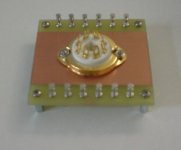
* Signal-Path Components[~$400] - I recommend following the best-practices used by Atma-Sphere Music Systems in construction and employ point-to-point wiring. To simplify and modularize the point-to-point wiring of the M-60, I suggest the use of single octal-socket terminal/turret boards such as the IAG TB-18's (Product Details) at about $17/each (see attached spreadsheet and illustration); we'll need 12 units per monblock (one for each tube). This approach allows us to pre-assemble each tube with the nearby components in the schematic, then simply install the "module" into the chassis. The pair of V-Cap Teflon coupling capacitors are an upgrade offered by Atma-Sphere and are used to bridge the input stage with the driver stage at almost $70/each. Add in the remaining Vishay precision metal-film resistors and Caddock metal-film power resistors, Zener diodes, film-type capacitors, etc., and we're up to about $380-$400 for the signal-path components (excluding vacuum-tubes). I use the usual suspects for DIY parts-vendors such as Digi-Key (DigiKey Corp. | Electronic Components Distributor | United States Home Page), Mouser (Mouser Electronics - Electronic Component Distributor) and Newark (US - Electronic Components Distributor | Newark.com).
* Vacuum Tubes [~$180-$320] - the necessary complement of vacuum-tubes (four 6SN7's, eight 6AS7's) can be procured from a number of sources. Some of my personal favorites are Tube Depot (Welcome to TubeDepot.com!), Tube Store (thetubestore.com Audio and vacuum tubes for your amplifier.) and Antique Electronic Supply (Antique Electronic Supply). The full complement of tubes from these sources varies between $180 up to about $250 (depending upon grade of tube specified). Of course, for a modest premium, you could just order the full set of tubes directly from Atma-Sphere Music Systems for about $320; that approach would safely ensure that the tube complement was appropriate for use in the M-60...
* Chassis Components [~$300] - This is the area where we'll likely see the largest divergence among those DIYaudio members who elect to build a pair of M-60's. As a long-term owner of Audio Research equipment, I'm heavily imprinted with the enclosed black anodized-aluminum lab-equipment chassis with clear anodized aluminum front-panel and black rack-mount handles. Therefore, I house my audio projects in a 14-Series chassis from Par-Metal (Par-Metal). I construct the internal structure for holding power-transformers, terminal-boards, etc., from pre-cut sheet aluminum and pre-cut aluminum bars ordered from Online Metals (Online Metal Store | Small Quantity Metal Orders | Metal Cutting, Sales & Shipping | Buy Steel, Aluminum, Copper, Brass, Stainless | Metal Product Guides at OnlineMetals.com). I usually have my front-panels and rear-panel overlays CNC-milled and engraved at Front Panel Express (Front Panel Express - Custom Front Panels with free Front Panel Designer*-*Home). The end-result is wickedly cool-looking DIY audio components.
Now that we have defined the unique-to-the-M-60 "big-ticket" power-supply components for the M-60 mono-block power-amplifier, I've defined an initial parts-cost estimate of ~$1200-$1500/mono-block. The following is the cost breakdown:
* Power Supply Components [~$500] - employing the Antek toroidal power-transformer models documented earlier in this thread, Hammond power-supply chokes, Nichicon high-reliability/105-degree-Centigrade power-supply capacitors and Solen polypropelene film-type power-supply decoupling capacitors, the estimated component costs for the M-60 power-supply is $502.75 (see attached Excel spreadsheet).
* Signal-Path Components[~$400] - I recommend following the best-practices used by Atma-Sphere Music Systems in construction and employ point-to-point wiring. To simplify and modularize the point-to-point wiring of the M-60, I suggest the use of single octal-socket terminal/turret boards such as the IAG TB-18's (Product Details) at about $17/each (see attached spreadsheet and illustration); we'll need 12 units per monblock (one for each tube). This approach allows us to pre-assemble each tube with the nearby components in the schematic, then simply install the "module" into the chassis. The pair of V-Cap Teflon coupling capacitors are an upgrade offered by Atma-Sphere and are used to bridge the input stage with the driver stage at almost $70/each. Add in the remaining Vishay precision metal-film resistors and Caddock metal-film power resistors, Zener diodes, film-type capacitors, etc., and we're up to about $380-$400 for the signal-path components (excluding vacuum-tubes). I use the usual suspects for DIY parts-vendors such as Digi-Key (DigiKey Corp. | Electronic Components Distributor | United States Home Page), Mouser (Mouser Electronics - Electronic Component Distributor) and Newark (US - Electronic Components Distributor | Newark.com).
* Vacuum Tubes [~$180-$320] - the necessary complement of vacuum-tubes (four 6SN7's, eight 6AS7's) can be procured from a number of sources. Some of my personal favorites are Tube Depot (Welcome to TubeDepot.com!), Tube Store (thetubestore.com Audio and vacuum tubes for your amplifier.) and Antique Electronic Supply (Antique Electronic Supply). The full complement of tubes from these sources varies between $180 up to about $250 (depending upon grade of tube specified). Of course, for a modest premium, you could just order the full set of tubes directly from Atma-Sphere Music Systems for about $320; that approach would safely ensure that the tube complement was appropriate for use in the M-60...
* Chassis Components [~$300] - This is the area where we'll likely see the largest divergence among those DIYaudio members who elect to build a pair of M-60's. As a long-term owner of Audio Research equipment, I'm heavily imprinted with the enclosed black anodized-aluminum lab-equipment chassis with clear anodized aluminum front-panel and black rack-mount handles. Therefore, I house my audio projects in a 14-Series chassis from Par-Metal (Par-Metal). I construct the internal structure for holding power-transformers, terminal-boards, etc., from pre-cut sheet aluminum and pre-cut aluminum bars ordered from Online Metals (Online Metal Store | Small Quantity Metal Orders | Metal Cutting, Sales & Shipping | Buy Steel, Aluminum, Copper, Brass, Stainless | Metal Product Guides at OnlineMetals.com). I usually have my front-panels and rear-panel overlays CNC-milled and engraved at Front Panel Express (Front Panel Express - Custom Front Panels with free Front Panel Designer*-*Home). The end-result is wickedly cool-looking DIY audio components.
Attachments
atmasphere> Just to be clear. You're saying run the heaters on the output tube supplies? Not an extra secondary but actually on the 140V? I thought the heaters were rated 6.3V?
VDC=VAC/sqrt(2);
It sounds familar...
MarkusG,
The filament heaters are still AC-powered separately from the DC voltage applied across the triode tube elements.
The formula for caculating DC voltage is:
VDC=VAC*sqrt(2)
atmasphere,
Is my new interpretation (single 99VAC secondary winding, providing 140VDC power-supply for each "phase" of the "floating" output stage power-supply) correct?
Thanks in advance!
Yes. In this way, the output is true push-pull, just like a transformer-coupled amplifier. That is to say, we don't have a cathode drivings the speaker in tandem with a plate. The output impedance is the same whether in push or in pull, if you don't mind the simplified explanation
Yes. In this way, the output is true push-pull, just like a transformer-coupled amplifier. That is to say, we don't have a cathode drivings the speaker in tandem with a plate. The output impedance is the same whether in push or in pull, if you don't mind the simplified explanation
atmasphere,
Thanks for clarifying my misunderstanding about the power-supply structure; this information will permit us to use only one transformer to power both "floating" power supplies! This information also brings my estimated power-dissipation for a powered-up M-60 into alignment with the published specifications for the product on the Atma-Sphere Web site, so I'm more comfortable that I've now got my head wrapped around the M-60 gestalt.
I just love the operational symmetry of the output stage; this topology is just too cool; again, thank you for sharing this information for non-commercial use by DIYaudio members!
To the forum-members, my initial parts-cost estimate (posted a bit earlier in this thread) assumed this new understanding of the power-supply structure. A power-supply schematic that incorporates the off-the-shelf components for a buildable implementation will be forthcoming once I can satisfy a peak in demands from my "day job"...
YaHoooooooooooooo!! We're in rapt attention at the prospect.
Thank you!
YaHoooooooooooooo!! We're in rapt attention at the prospect.
Thank you!
tympani1d,
You're quite welcome! I'm about half-way through the first-draft power-supply schematic (I grabbed a few cycles for drafting the schematic over the weekend, while my family slept...
), so it won't be too much longer before I can post the diagram.To the DIYaudio forum members following this thread,
I need your assistance; can anyone read/identify the U1 part-designation in the M-60 power-supply schematic post by "atmasphere"? I know there are file-size limitations on posts, but the image resolution makes it impossible for me to clearly read the part designation on U1 (all I can ascertain is "V<something>-<three-characters>"...). If no one can identify the regulator chip, "U1", I'll just insert an inductor as a place-holder in the first-draft schematic.
Thanks in advance!
Its a VB-408- A high voltage regulator. We found that we had to use them when the amp had the switch in the class AB position. There was so much variation on the plate of V4, the regulator was needed to make the amp play right.
If you use a 3K 3watt resistor instead, the amp will work perfectly as long as you do not include any of the 'class AB' elements shown in the schematic.
The history is that when this amp was made, we had a distributor that wanted the extra feature installed. No-one ever seems to have used it. Fortunately, we're not involved with that mess these days and so we just do the 'class A' circuit exclusively. For that, the resistor above works fine- from 107 to 125V you cannot measure or hear any change in performance of the circuit.
All I can make out is V?-400. the ? can be a 0,O,D or B I think?
I'm fairly certain of the 400.
MarkusG,
Thanks, that's about all that I can see as well; hopefully, someone will be able to give us a more definitive answer as to the identity of U1...
In the interim, I'll just include an inductor as a place-holder for the unknown/unidentified three-terminal regulator circuit in the initial draft of the power-supply schematic. My current assumption is that the U1 circuit is a refinement of the driver stage operations, but that's just a guess on my part...
Its a VB-408- A high voltage regulator. We found that we had to use them when the amp had the switch in the class AB position. There was so much variation on the plate of V4, the regulator was needed to make the amp play right.
If you use a 3K 3watt resistor instead, the amp will work perfectly as long as you do not include any of the 'class AB' elements shown in the schematic.
The history is that when this amp was made, we had a distributor that wanted the extra feature installed. No-one ever seems to have used it. Fortunately, we're not involved with that mess these days and so we just do the 'class A' circuit exclusively. For that, the resistor above works fine- from 107 to 125V you cannot measure or hear any change in performance of the circuit.
atmasphere,
Excellent! Thank you for the component-ID as well as the history of the sub-circuit. That sort of background is incredibly useful, providing insight into the design process for those of us who are students of the art of engineering.
Configuring the M-60 in "hot-rod" mode (i.e., no Class-A/Class-AB switch) greatly simplifies the power-supply schematic, permitting me to omit the Class-AB "half-power" configuration of the power-transformer primary circuits. The siimplification means that we can also delete the relavent resistors from the bias voltage-divider circuit for the output stage. So, only full-throttle, fire-breathing, Class-A2 M-60's for us!
atmasphere already told us one post above.
VB-408.
Yeah, that's part of the fun of asynchronous communications...
The "good news" is that, since I can now delete the "Class-A/Class-AB" circuitry, I get to seriously simplify the power-supply schematic. Without the additional complexity, I may be able to complete the power-supply schematic yet today...
M-60 OTL Power-Supply Schematic (v1.0)
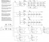
Here's the first-draft of the M-60 OTL power-supply schematic for this thread. I have incorporated the changes that have accrued during the discussion, including "hot-rod" mode (deletion of the Class-A/Class-AB switching), deletion of the B+ regulator for the driver stage, power-supply rail-decoupling capacitors, etc. It's like Ragu Spaghetti Sauce, "It's in there...".
I'm posting both the JPEG and PDF versions of the M-60 "hot-rod" power-supply schematic; the JPEG is potentially a bit marginal on the display resolution presented (but it meets the forum's file-size requirements), so the PDF will offer a clearer view of the schematic in those cases where the JPEG is insufficient.
Let the fun begin...
Attachments
Last edited:
Awsome.
It's only now that it hits me. There is some serious hardware going into this build.
7... yes seven separate transformers per monobloc.
Thats 14 transformers per stereo pair.
Gawd da*n that's a lot.
The shematics are clean and simple however so even n0ob like me should be able to pull it off.
No need for PCBs either, always a plus for the DIY crowd.
Awsome.
It's only now that it hits me. There is some serious hardware going into this build.
7... yes seven separate transformers per monobloc.
Thats 14 transformers per stereo pair.
Gawd da*n that's a lot.
Agreed! Fourteen power-transformers is quite a pile of energized iron, isn't it?
The power-supply clarification from "atmasphere" (regarding the total voltage applied to the output stage tubes) did allow me to delete a second output-stage power-transformer that I had originally thought would be necessary. But those filament heater power-transformers just keep multiplying like rabbits...
None of the usual toroidal power-transformer vendors (Plitron, Avel-Lindberg, Antek, etc.) offer any 6V models with a higher current capacity than the 50VA-rated units specified, so we have to parallel the filament transformers. Then I had to add one more to allow the inter-dependent application of the filament power ("Standby" mode) and the high-voltage power ("Operate" mode).
The shematics are clean and simple however so even n0ob like me should be able to pull it off.
Thanks! I was trying to visually convey the elegant simplicity of even the power-supply of the M-60. As you've noted, there's really nothing terribly complex here, just a very large number of components to harness.
No need for PCBs either, always a plus for the DIY crowd.
Yes, I prefer to construct my DIY projects using a point-to-point wiring methodology. Those IAG single-socket terminal-boards really make the assembly straightforward as well as provide a really nice look-and-feel to the guts of our projects. The point-to-point approach greatly facilitates the inevitable modifications in a clean, non-destructive manner.
M-60 OTL Revised Signal-Path Schematic
Now that we've got a first-draft schematic for the M-60 power-supply posted for review, I'll start work on the complementary revised M-60 signal-path schematic that reflects the "hot-rod" M-60 configuration (deleted Class-A/AB circuitry, increased bias current for the input-stage, etc.). I'll crunch the diagram as soon as time permits...
Now that we've got a first-draft schematic for the M-60 power-supply posted for review, I'll start work on the complementary revised M-60 signal-path schematic that reflects the "hot-rod" M-60 configuration (deleted Class-A/AB circuitry, increased bias current for the input-stage, etc.). I'll crunch the diagram as soon as time permits...
- Home
- Amplifiers
- Tubes / Valves
- What tubes for a OTL tube amp?