That 75V AC rating on the secondaries of the B+ supply for the output tubes seems a bit low to me. Typo?
Stancor used to make a 20-amp filament transformer that did the job nicely, but it didn't have a 235V capability. The Hammond 266V6B is rated at 20Amps also.
atmasphere,
The 75VAC@5.3A per secondary winding is correct; that was the "best-fit" combination of voltage/current that I was able to locate to power the output stage "floating" power-supplies.
In your post #60 in this thread, you stated that it was OK to run with somewhat lower voltage (down to 100VDC). The currently designated transformer would give about 106VDC; will this be problematic?
Stancor TGC175-12 (28A@6.3V) and TGC130-12 (20.60V@6.3V) looks to be in the right area.
Yes, both Stancor and Hammond offer filament transformers with high-current capacities, so that approach is certainly an option. However, those transformers are all of E-I core construction, which I have always found to be prone to emitting mechanical hum; that's why I tend to focus on the use toroid power-transformers (combined with a good DC-trap circuit). A custom-wound toroid could be specified that would allow us to have just one filament power-transformer; the cost would likely be comparable to the five inexpensive 50VA-rated transformers currently specified in the schematic. Depending upon the response from "atmasphere" regarding the voltage output of the currently specified output-stage power-transformer, we may need to consider a custom-wound unit for that device as well...
")
But wasn't the T2 supposed to be two separate transformers? Not just separate secondaries?
We only need independent/floating power-supplies for the output stage, so using a single power-transformer with dual secondaries meets the requirement. However, it would be simple enough to add a second output-stage power-transformer to the power-supply design if you want to minimize any potential for cross-talk between the secondaries. It's a DIY project, which gives us the lattitute to do whatever we feel is needed to optimize the audio characteristics...
That 75V AC rating on the secondaries of the B+ supply for the output tubes seems a bit low to me. Typo?[...snip]
atmasphere,
Perhaps more to the point; would running with 75VAC secondaries for the output stage power-supplies be sub-optimal from a music reproduction standpoint? Those of on the thread are, of course, interested in maximizing the music reproduction capabilities of our DIY M-60's...
I see that we can get off-the-shelf 600VA-rated toroids with dual 50VAC@6A secondaries (Antek - AN-6450); if we were to use one of these transformers per "phase" of the Circlotronic output stage in a "stacked" secondary configuration, that would give us 140VDC@6A for each of the "floating" output stage power-supplies. It would double the number of power-transformers needed to provision the output stage, but the important question is, "Would this approach be better from a sound-quality viewpoint?". If so, I'm more than happy to revise our proposed power-supply design.
I've also submitted a price quote request to Toroid Corporation (I've used these folks for customer transformers) for a dual-secondary 99VAC@6A power-transformer (equipped with 117/230VAC reconfigurable, dual-primaries), just to see where the price range would fall. It's possible the price for a single custom-wound toroid might be less expensive than two of the off-the-shelf transformers that I just described.
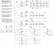
M-60 OTL Power-Supply Schematic (v1.1)
OK, apparently I experienced a Homer-Simpson-esque "Doh!" moment when originally searching for appropriate off-the-shelf power-transformers for the M-60 mono-block project. At the heart of the matter, I failed to consider the use of stacked secondaries in order to more closely approximate the design center provided by the custom power-transformers used in the commercial M-60 project. Mea culpa...
So, attached is the revised M-60 power-supply schematic (again, in both JPEG and PDF formats) that uses a pair of Antek AN-6450 (Antek - AN-6450) to power the M-60 "floating" output stage power-supplies. Each of these power-transformers provide a combined 100VAC (50+50VAC) output, resulting in a 140VDC@6A output. Obviously, I'll need to cook-up an updated parts-list, but I'll get that posted soon.
Everyone good with this change? Any rational objections?
Attachments
I guess a few more bucks won't make any huge difference. Looking good.
Agreed; we're in pursuit of a state-of-the-art topology, so there's really no point in cutting any corners during the implementation; in for a penny, in for pound...
I'm running out of questions and things to comment on, in a way maybe that's a sign of the design reaching maturity?
There's undoubtedly more "lessons learned" that are still to be gleaned from the production implementation of the M-60; Atma-Sphere has been methodically refining their core balanced-differential topology for literally decades. And "atmasphere" (whom I suspect may well be Ralph Karsten, founder/master-technologist of Atma-Sphere Music Systems...
) has certainly been amazingly generous and forthcoming in sharing information with the DIYaudio community. However, given the elegant simplicity that's "hidden in plain view" during this project, I agree that our current power-supply design is quickly coming into alignment with the overall design gestalt of Atma-Sphere Music Systems (but that may be overly presumptuous on my part...). Actually there's one thing that keep bothering me. Please explain this to me.
Reading the data sheet for a Svetlana 6AS7 it reads plate dissipation 13W max.
I assume that's for one channel and we have two per tube i.e 26W per tube.
8 tubes makes that 208W.
140VDC @ P=UI -> I=1.5A
AN-4450 is rated 2x50V | 4.0A
Why not go with the smaller cheaper transformer? What am I missing?
Maybe it's even possible to run the AN-3245? But then we're loosing voltage, only 2x45VAC | 3.3A.
If possible to go with the smaller transformers we'd be cutting the cost in a big way.
mullardel34:OK, apparently I experienced a Homer-Simpson-esque "Doh!" moment when originally searching for appropriate off-the-shelf power-transformers for the M-60 mono-block project. At the heart of the matter, I failed to consider the use of stacked secondaries in order to more closely approximate the design center provided by the custom power-transformers used in the commercial M-60 project. Mea culpa...
So, attached is the revised M-60 power-supply schematic (again, in both JPEG and PDF formats) that uses a pair of Antek AN-6450 (Antek - AN-6450) to power the M-60 "floating" output stage power-supplies. Each of these power-transformers provide a combined 100VAC (50+50VAC) output, resulting in a 140VDC@6A output. Obviously, I'll need to cook-up an updated parts-list, but I'll get that posted soon.
Everyone good with this change? Any rational objections?
First: Thank you for your extraordinary work and passion for all of us!!!
Second: Back to the class AB stuff for a moment. Will the previously posted power supply sch. and parts list work should one wish to go the AB route? If not, would you and atmashere be willing to give us the full panopoly of options in detail that one may build them?
Back to lurker mode..... and THANK YOU

Last edited:
stevekendalI just joined today and havent read all the 140+ posts in this topic, but here in the UK, 4 x EL84 and a few ECC83 would be a popular choice in answer to the original question. Hope this is helpful,
Welcome!!
Actually there's one thing that keep bothering me. Please explain this to me.
Reading the data sheet for a Svetlana 6AS7 it reads plate dissipation 13W max.
I assume that's for one channel and we have two per tube i.e 26W per tube.
8 tubes makes that 208W.
140VDC @ P=UI -> I=1.5A
The M-60 output stage targets each 6AS7 triode section to run at an idle bias value of 60mA. Each "phase" of the output stage floating power-supplies places 140VDC across the 6AS7's. The result is that each 6AS7 triode section has a standing plate power-dissipation of 8.4-Watts (60mA x 140VDC). The 6AS7 is rated for a maximum plate power-dissipation of 13-Watts per triode section (26-Watts per 6AS7), so the M-60 output stage is only running the output tubes at about 65% of rated power-dissipation capacity. While my own background of conservative engineering would usually lead me to design to a somewhat lower percentage of power-dissipation, the 30+ year track history of the production M-60 power-amplifiers certainly demonstrates that the specified configuration does not impair long-term reliability (quite the opposite, in fact...). So far, so good...
AN-4450 is rated 2x50V | 4.0A
Why not go with the smaller cheaper transformer? What am I missing?
Maybe it's even possible to run the AN-3245? But then we're loosing voltage, only 2x45VAC | 3.3A.
If possible to go with the smaller transformers we'd be cutting the cost in a big way.
The Circlotronic/bridged output stage is still a relatively new concept to me, so my understanding may be incomplete; caveat emptor...
The Class-A2 mode of operation employed in the M-60 output stage requires that we consider a couple of non-intuitive (at least to me...) aspects of 6AS7 current-delivery to the loudspeakers. The M-60 output stage leverages the transient current-delivery capacity of the 6AS7, which is not specified in the datasheet. The total output-stage idle bias current is 480mA per "phase" of the output stage, so a push-pull Class-A output stage would only be able to deliver 960mA (peak), or about 3.7-watts (RMS) to the output. But, the "secret sauce" is the fact that the M-60 output stage makes use of grid-conduction on the 6AS7's (the "2" suffix in "Class-A2" indicates grid current flows for some part of the cycle). Driving the 6AS7's into grid-conduction allows us to "squeeze" a peak output current delivery of up to 300mA per triode section, all while each 6AS7 section remains in conduction throughout the output waveform cycle (the definition of Class-A operations). Therefore, the Class-A2 output stage of the M-60 can deliver up to 2.4A of current per "floating" power-supply, so each "phase" of the "floating" power-supplies much provision at least 2.4A's of current capacity.
My own engineering "best practices" lead me to specify components that are operated at less than 50% of their RMS-rated capacities. Designing power-supplies for a nominal Class-A output stage, the M-60's standing bias current of 60mA per 6AS7 triode section would lead us to believe that we only need to provision 240mA's of current capacity within each "floating" power-supply, so a power-transformer with a secondary rated for 500mA would be sufficient for conservative operation. Under these circumstances, the smaller power-transformers mentioned would be OK.
However, the Class-A2 mode of operation in the M-60 output stage alters some of the baseline power-supply configuration considerations. To ensure Class-A operation, the power-supply must provision sufficient current capacity to satisfy the peak current demands; the peak Class-A2 current need is 2.4A's, so to conservatively operation the M-60 output stage the power-transformer should be rated for at least 5A's of current delivery. Under the constraints just outlined, smaller power-transformers would likely "work", but those devices would be stressed beyond the bounds of conservative operation (IMHO).
mullardel34:
First: Thank you for your extraordinary work and passion for all of us!!!
Second: Back to the class AB stuff for a moment. Will the previously posted power supply sch. and parts list work should one wish to go the AB route? If not, would you and atmashere be willing to give us the full panopoly of options in detail that one may build them?
Back to lurker mode..... and THANK YOU
tympani1d,
Thanks for your kind words! As to the Class-A/AB switch functionality, there are a number of "moving parts" that have to be properly enmeshed/engaged; that's a big part of the reason that I opted for the "hot-rod"/Class-A-only M-60 configuration...
The only schematic that includes the Class-A/AB switching functionality is the schematic for the production M-60, which was posted by "atmasphere" earlier in this thread. Neither of the power-supply schematics posted by me include the Class-A/AB capability.
The Class-A/AB switching functionality appears to have two primary elements:
* Reconfiguration of primary-windings for "floating" power-supplies - the Class-AB mode only energizes half of the primary windings of the "floating" power-supply transforms; the input/driver stage power-supplies are unaltered.
* Decreased fixed-bias for 6AS7's - Class-AB mode switches-in additional resistors into the voltage-divider that establishes the fixed-bias voltage for the output tubes, resulting in more negatively-biased grids for the 6AS7's.
The power-transformers that we've specified for the DIYaudio M-60 (selected to enable both 117/230VAC operations) could accommodate the necessary reconfiguration for 117VAC (switch the AC-line voltage input to only drive one of the two primary windings), but I don't see any means of configuring the Class-AB functionality for 230VAC environments by manipulating the transformer primaries.
Hmmm, I suppose that, leveraging the dual-secondary power-transformers that we've recently specified for the DIYaudio M-60's "floating" power-supplies, you could use a switch to only employ one of the 50VAC secondaries during Class-AB mode (using half of the secondary voltage would be the equivalent to driving only half of the primary voltage, right?
). The dual-secondary nature of the DIYaudio M-60 power-transformers would enable the Class-A/AB switching, regardless of 117/230VAC primary-winding configuration. Just a thought; your mileage may vary... Better PSU output stage curent source mean more stable output stage operation and less heat from asociated transformer.1A per phase is minimum but 2A is quit enough.Important thing is INTERWIRING under the chasis,thats is Crucial in this circlotron amps.Here ATMASPHERE manufacture paid special atention during the desing and asembly proces.BTW ATMASPHERE M60 amps are so Simply(Electronicaly)designed, Special older models(I have seen other manufacturer Cyrclotron Amps design thats are To complex for DIY).But Simplycity(NOT Owersymplycity) is the key point of good sounding Tube amp and longlast.Good luck
Better PSU output stage curent source mean more stable output stage operation and less heat from asociated transformer.1A per phase is minimum but 2A is quit enough.Important thing is INTERWIRING under the chasis,thats is Crucial in this circlotron amps.Here ATMASPHERE manufacture paid special atention during the desing and asembly proces.BTW ATMASPHERE M60 amps are so Simply(Electronicaly)designed, Special older models(I have seen other manufacturer Cyrclotron Amps design thats are To complex for DIY).But Simplycity(NOT Owersymplycity) is the key point of good sounding Tube amp and longlast.Good luck
As I noted, power-transformers for the "floating" power-supplies with less current-delivery capacity would "work", but it would appear to be sub-optimal to me. I would recommend that we not unnecessarily constrain the M-60 design/topology during the build-out ($20-$30/transformer just doesn't seem worth the potential performance compromise from my standpoint, but that's just an opinion...). However, the DIYaudio forum members are certainly free to implement the design according to their own engineering muse...
Last edited:
tympani1d,
Thanks for your kind words! As to the Class-A/AB switch functionality, there are a number of "moving parts" that have to be properly enmeshed/engaged; that's a big part of the reason that I opted for the "hot-rod"/Class-A-only M-60 configuration...
The only schematic that includes the Class-A/AB switching functionality is the schematic for the production M-60, which was posted by "atmasphere" earlier in this thread. Neither of the power-supply schematics posted by me include the Class-A/AB capability.
The Class-A/AB switching functionality appears to have two primary elements:
* Reconfiguration of primary-windings for "floating" power-supplies - the Class-AB mode only energizes half of the primary windings of the "floating" power-supply transforms; the input/driver stage power-supplies are unaltered.
* Decreased fixed-bias for 6AS7's - Class-AB mode switches-in additional resistors into the voltage-divider that establishes the fixed-bias voltage for the output tubes, resulting in more negatively-biased grids for the 6AS7's.
The power-transformers that we've specified for the DIYaudio M-60 (selected to enable both 117/230VAC operations) could accommodate the necessary reconfiguration for 117VAC (switch the AC-line voltage input to only drive one of the two primary windings), but I don't see any means of configuring the Class-AB functionality for 230VAC environments by manipulating the transformer primaries.
Hmmm, I suppose that, leveraging the dual-secondary power-transformers that we've recently specified for the DIYaudio M-60's "floating" power-supplies, you could use a switch to only employ one of the 50VAC secondaries during Class-AB mode (using half of the secondary voltage would be the equivalent to driving only half of the primary voltage, right?
Yes, I see the point.
I'm still fence riding as to "Hot Rods to Nirvana" or build up to switch for touring suspension on a quite ride in the clouds, as it may be and mood strikes!!

Last edited:
Yes undercurent transformers well work but reproduced SOUND well be afected negative(special in dynamic).2A per phase is ok beacoose you Allready hawe storage energy in smoothing filtter(electrolytic capacitor).About Symplycity of this amps:Basicly here is TWO independent SE(Single End) Cathode Folower OTL Amps,working independent out of phase,joined together in Unique Electronical Junction Point(CIRCLOTRON or here in Europa PUSH PULL PARALLEL)) wher COMON is only LOAD(SPEAKER) and CHASIS.The results are UNIQUE SUOND DEFINITION.The Best way to Implement this Power amp is to drive hem with Balanced(Diferencial, out of phase ) signal from Preamp Via XLR (600 ohm)cables or from PC soundcard(with diferencial out)or DAC with same DIF out.Then Input stage is only Gain Stage.In case You drive hem via RCA(unbalanced)input Input stage is Gain Stage+Phase Inverter(Sonicaly small diferences)
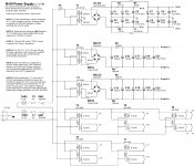
M-60 OTL Power-Supply Schematic (v1.1AB)
tympani1d,
Well, high-quality music reproduction is all about "enjoying the ride"...
Following-up on the thoughts I offered in an earlier post about implementing a Class-A/AB switch, I've attached a revised M-60 power-supply schematic that includes the power-supply elements of the mode-switching for the output stage; the additional switch, SW3(a/b), implements the necessary changes to the "floating" power-supplies for the output stage.
For those interested in including the Class-A/AB switching functionality, please review the schematic and see if it makes sense as an equivalent means of dropping the voltage across the output tubes as energizing only half of the transformer primaries (as documented in the original M-60 power-supply schematic posted by "atmaphere"). This circuit change, combined with the concurrent altering of the fixed-bias voltage with other sections of the switch, SW3, is how the M-60 is reconfigured for Class-AB operations. Man, that's a couple of ugly sentences, isn't it?
Yes, I see the point.
I'm still fence riding as to "Hot Rods to Nirvana" or build up to switch for touring suspension on a quite ride in the clouds, as it may be and mood strikes!!
tympani1d,
Well, high-quality music reproduction is all about "enjoying the ride"...
Following-up on the thoughts I offered in an earlier post about implementing a Class-A/AB switch, I've attached a revised M-60 power-supply schematic that includes the power-supply elements of the mode-switching for the output stage; the additional switch, SW3(a/b), implements the necessary changes to the "floating" power-supplies for the output stage.
For those interested in including the Class-A/AB switching functionality, please review the schematic and see if it makes sense as an equivalent means of dropping the voltage across the output tubes as energizing only half of the transformer primaries (as documented in the original M-60 power-supply schematic posted by "atmaphere"). This circuit change, combined with the concurrent altering of the fixed-bias voltage with other sections of the switch, SW3, is how the M-60 is reconfigured for Class-AB operations. Man, that's a couple of ugly sentences, isn't it?
Attachments
I was gearing up to write something lengthy but banat probably said it better than me.
It was tricky with the extra amperage, definately not covered in the tubes 101 class.
However the peak currents (5A) are peak currents and the caps should be able to take some of the load off the transformer, right?
I want the best sound possible to and I'm also a fan of over engineering but only for so long.
Let's consider the AN-4450?
Is there really any reason not choosing this cheaper transformer? If there is I'll happily go along with the beefier cousin but if it's ok I'd be glad to save a few $$$.
I was gearing up to write something lengthy but banat probably said it better than me.
It was tricky with the extra amperage, definately not covered in the tubes 101 class.
However the peak currents (5A) are peak currents and the caps should be able to take some of the load off the transformer, right?
Engineering often plays-out as a zero-sum game; keep in mind that the "pi" filters for the output-stage power-supplies will limit the rate at which the capacitors can be recharged (this is the "pound of flesh" extracted in exchange for a higher level of isolation from the AC-line cruft). If the current capacity of the power-transformer is limited, the result will be further "sag" of the voltage applied across the output tubes during higher output levels. The endpoint would be a form of dynamic compression of the output signal.
Conservative engineering for a Class-A output stage would normally lead us to provision the power-supply for the anticipated peak current demands in order to maintain Class-A operations under all conditions. The Class-A2 mode of the M-60 Circlotronic output stage complicates the design considerations (i.e., 60mA idle current per triode section, peak current delivery of 300mA per triode section with grid-conduction). Since I haven't built one just yet, I'm designing the power-supply on the conservative side of things to keep anyone building this project from "driving off into the weeds"...
I want the best sound possible to and I'm also a fan of over engineering but only for so long.
Let's consider the AN-4450?
Is there really any reason not choosing this cheaper transformer? If there is I'll happily go along with the beefier cousin but if it's ok I'd be glad to save a few $$$.
You are absolutely free to plug-in any of the Antek AN-x450-series power-transformers (the output voltage is the same for all models, there's simply a difference in the current output available); the Antek AN-x450 transformers give us the flexibility to plug-and-play various models in order to scale-up or scale-down the M-60 to meet a range of power-output levels (as an example, I'm planning to build an M-60-based dual-mono pre-amplifier as my first implementation of the fully-balanced Circlotronic OTL topology, so I'm planning to use the AN-4450 to power a single pair of 6AS7's per channel). I simply want to ensure that everyone has the information to make an informed decision. If you're comfortable using the AN-4450 power-transformers, know that they will absolutely "work". Perhaps "atmasphere" will weigh-in with his operational experiences...
Further, the M-60 design makes it quite simple to plug-in or remove pairs of output tubes without disturbing the output stage operations (other than reducing the current-drive available for the loudspeaker load). So, it would be a straightforward experimental process to select your power-transformer of choice, then to start with the installation of one pair of 6AS7's, measure output performance, install the next pair of 6AS7's and "rinse and repeat" until you observe a non-linear increase in output power. You would then have empirical evidence to specify the power-transformer current capacity needed to deliver the targeted output-power levels.
Last edited:
ok, fair enough.
Another interesting part is the ease of which you can change transformer as well.
In my case this thread started with me looking for a 20 or so W amp.
The AN-4450 will no doubt drive 4 tubes, probably 6 as well and possibly even 8?
I guess I could do it that way?
Go for the smaller one and start off with 4 tubes. If there's an output impedance issue or poweer issue I can add tubes and if Things get really bad it's easy enough to change transformers.
It truly is a super desig with its modularity.
- Home
- Amplifiers
- Tubes / Valves
- What tubes for a OTL tube amp?