I don't need to go quite that far in efficiency, but class D is the ultimate for that.Well for my part the OTL has so much magic that ineffiency dosent matter. Use PWM (class D) amp if that is a concern...IMHO
Hi morpheous@valvemaniacuk
sorry to bother you, I saw in a post that you built a Lite Audio LS26
I'm also building Lite Audio LS26 and I have to buy the transformer for the power supply. What transformer did you buy? Can you tell me the features?
Ciao Francesco.
Apologies for the delay in replying. I haven't been on the forum for some time and my account wasn't active. All sorted now thanks to the team.
IIRC, I bought an R core transformer that the ebay seller was offering to go with the LS9D power board that I used. If you need more info, I'll dig out the amp and get a few photos for you. It simply had all the windings needed for the LS9D, so made for a straightforward installation
Cheers,
Steve.
I have build both types, the totempole (futterman) and the circlotron. The totempole must use pretty high amounts of teedback and the circlotron can be made wit hout feedback (in both cases I mean global feedback).
To my ears, the circlotron is more natural, but then again there are many ways to Nirvana
To my ears, the circlotron is more natural, but then again there are many ways to Nirvana
Sure! But I suspect you already know where I come down on this topic. The M-60 (which is the amp used in this case) was more 3D, sounded faster but wasn't bright and played the bottom end with more control and impact. The Futterman amp seemed to have a tiny sound stage by comparison.Do you remember anything notable about the experience?
I have build both types, the totempole (futterman) and the circlotron. The totempole must use pretty high amounts of teedback and the circlotron can be made wit hout feedback (in both cases I mean global feedback).
To my ears, the circlotron is more natural, but then again there are many ways to Nirvana
True, that.
Yes, atmasphere, you've done a good job.
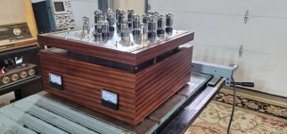
I just built a Rosenblit version, only slightly modified, with most changes done to the bias supply and using a 6J5GT rather than the 2nd 6SN7GTB (yes I know why he chose the 6SN7 B version) and then changed the 12AX7 to a 12AU7 using both triodes (RCA Clear top). It only uses 4 6AS7GAs per channel.
Having learned a lot about the circuit, I decided to take it up a notch. So the 2nd one uses 6 6AS7GAs per channel (brings in that missing bass) but also incorporates a 260V regulated bias supply and individual bias adjustments per pair on both the + and - sides. . It is a heavy son-of-a-gun weighing in at over 60lbs.. I used individual transformers for the + and - rails running at 160V (+160 &-160) and individual filament transformers, per channel. It, however can run all of the versions of 6AS7, 6336 and 6528, if the room gets too cold - otherwise the 6AS7GAs are quite enough (this ability accounts for much of the weight).
The first unit needed to have a fan added because, even with the tubes on top the IR radiated down into the enclosed area housing the filters. The 2nd unit has a hinged top so access to the components is much easier and the vent negates the need for a fan. The filters are all under the 2nd heatshield. Yes it has an unusual look . I call it the Up-Side-Down space heater, since the aluminum chassis is actually upside down.
I guess that I will have to build the M-60 clone if I want to find out for myself.
P.S. prefer the RCA type of 6AS7GA to all others - watch out some RCAs are GEs which are not the same.
Russ
https://www.russoldradios.com/
Attachments
Last edited:
I could never get the 6AS7GAs to hold up! They tended to be very prone to arcing. The 6AS7G far less so. If the tubes were NOS we found that running the filaments 4 days and nights before applying B+ had a significant affect on the tube life and arcing (at least this is so for the RCA 6AS7G). The Russian 6H13C is good with 3 days and nights but the Chinese 6N13PJ needs 4 days and nights. If B+ is applied the preconditioning process ends. This technique was documented in the 1959 edition of the AudioCylopedia in case you want to read about it (although there's not a lot more information than I've already mentioned).
I've been thinking recently that the smaller iterations of the Circlotron OTL will benefit from more feedback due to the tendency to use them with lower impedance speakers. Feedback has gotten a bad rap (causing brightness and harshness) on several accounts; one of them being that traditionally its applied to the cathode of the input tube, which isn't linear. So its distorted before it can do its job of reducing distortion (and output impedance).
But in our M-60 (and all our OTLs for that matter) the input voltage amplifier is a differential circuit. So the cathodes can't be used. This forced us to use the grids instead (the S-30 and M-60 both always used a tiny amount of feedback). This is a good thing because we simply mix the feedback with the incoming audio using a resistive divider network similar to how its done with opamps. The advantage of course is resistors are a whole lot more linear than the most linear tubes made. So the feedback is better able to do its job. But we never applied very much at all.
So my thinking has been to add a stage of gain between the differential cascode input and the cathode follower driver tube, and send the feedback to that stage of gain (rather than the input). The reasoning is more to reduce output impedance and distortion from the output section rather than the input. I was thinking of a 6SN7 or 12AU7/6CG7 for this task, using enough feedback to negate the gain of the tube. Since its a balanced circuit there would be two loops. Of course the loops would likely require a second order to prevent exceeding the phase margin (but that is also why I was not thinking of applying the feedback to the input voltage amplifier), but maybe not, since the amp is an OTL and doesn't have that many poles involved. The output section and the driver have really wide bandwidth so this really comes down to the poles introduced by the intermediate stage of gain (the 'feedback stage'???), which can be minimized if the circuit is designed for wide bandwidth.
This could allow the amp to behave as a Voltage source on many speakers, widening the choices available. It would not make it able to drive 4 Ohms with any more power of course, but at least its FR would be linear and distortion better controlled, hopefully without too much bifurcation on account of the feedback.
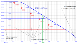
IMHO it`s nothing wrong to encircle the whole OTL amp (including balanced VAS) with balanced feedback loops , OLG have to be around 60dB and CLG have to be around 20dB ,that is possible since there`s no output transformer , also when the amplifier is set to unity gain(2Vpp in -2Vpp out) it must perform unconditionally stable ,
in the case of M-60 or S-30 only brand new very high gain balanced VAS stage need to be designed , driver and OPS don`t need to be modified at all, except only to add standard zobel RC network to output terminals .
in the case of M-60 or S-30 only brand new very high gain balanced VAS stage need to be designed , driver and OPS don`t need to be modified at all, except only to add standard zobel RC network to output terminals .
Guys, atmasphere,
I have not had a problem with arcing of the 6AS7GA unless I instigated it ;-) Setting up the Fetterman is like herding 24 cats (12X2). I incorporated a better monitoring circuit to help prevent - - miss-fires. And you can adjust bias on all of the tubes at once if you want to (once they have been balanced). I am running them at 120ma/pair or ~60ma ea.
What I have found to be as, if not more, important than gm indicated on your tester is warm-up time. A used tube can take a long time to get to near full power, where as a new tube can do it in a minute or less. If you pair up a new tube with a GOOD used tube - well - the cats get wilder. You can put two used tubes together, but you'll need to wait to set bias. If you try to get 60ma out of them in only a minute - there will be sparks later. I use a stop-watch with my tube tester and I will often test the tubes using what Hickok called a "Life Test". So, run the filaments at 5V. The NOS tube will not even notice BUT you will find those well used tubes quickly.
I have had a problem with arcing using 6528 tubes. I will need to install a slow start with B+ on a couple of seconds ramp-up.
I purchased "5 NOS " tubes on E-pay and received 2 with the fusable links open to either the plate or cathode. So somebody else also has problems with "sparks".
Russ
I am running them at 120ma/pair or ~60ma ea.
On my U-OTL, I am at 100mA for each 6080WA, that is to say 50mA per triode section at idle, under a plate to cathode voltage of 115VDC, that is to say less than 6W of plate dissipation at idle. At 10WRMS output, the current per triode reaches 72-73mA, so less than 9W plate dissipation (design max = 13W per triode). No arcing nor sparks, since these tubes are by design reasonably powered here, for safe operation and life expectancy, and yes : only 10WRMS output / 16R...
T
The less poles you have in the circuit, the better your chances are of a lower ordered feedback loop. A lot of feedback loops are simply a resistor from the output to somewhere at the input, but if the bandwidth allows this does open the amp to oscillation since the bandwidth of the output section is well into the 10s of MHz.IMHO it`s nothing wrong to encircle the whole OTL amp (including balanced VAS) with balanced feedback loops , OLG have to be around 60dB and CLG have to be around 20dB ,that is possible since there`s no output transformer , also when the amplifier is set to unity gain(2Vpp in -2Vpp out) it must perform unconditionally stable ,
in the case of M-60 or S-30 only brand new very high gain balanced VAS stage need to be designed , driver and OPS don`t need to be modified at all, except only to add standard zobel RC network to output terminals .
That is why I proposed sending the feedback to an intermediate Voltage amplifier rather then the input; the goal being lower output impedance rather than vanishingly low distortion. But if you don't mind complicating the math a bit, a 3rd order feedback loop should be able to work aright if you have two Voltage amplifiers in cascade. You really want to keep the ultrasonics out of that loop, without imposing phase shift...
The other issue is distortion must not rise with frequency once the feedback is in place. If it does, it will be heard as brightness and a touch of harshness.
IMO it is not so important if the OPS-BW is in the 10s of Mhz range , that`s actually one advantage ,but what`s important is to limit input signal BW at input of triodes grids to 20Khz using simple RC low pass filter , so any signal at input grids above 20Khz have to be atenuated gradually, also what is important inside of the amp is to not have phase shifting elements , in case of your amps that only two RC elements pair , two 0,1uF coupling caps in conjunction with two 1M bias resistors ,
here`s one basic graph , where I prefer~60dB OLG vs 20dB CLG ( 1000:10 voltage amplification ratio) , since IMO that`s one good compromise for relative small OTL amp working as voltage source , but I still think that for overall amp stability higher loadspeaker impedance have to be used anyway , for S-30 anything between 16 and 32 Ohm is a good choice .
here`s one basic graph , where I prefer~60dB OLG vs 20dB CLG ( 1000:10 voltage amplification ratio) , since IMO that`s one good compromise for relative small OTL amp working as voltage source , but I still think that for overall amp stability higher loadspeaker impedance have to be used anyway , for S-30 anything between 16 and 32 Ohm is a good choice .
Attachments
The other issue is distortion must not rise with frequency once the feedback is in place. If it does, it will be heard as brightness and a touch of harshness.
Yes, true and well described @atmasphere... When the tone in the treble turns from brightness to harshness, that's probably the most unpleasant, unforgivable flaw from an amp - at least to my ears !
That's why my little U-OTL doesn't have a general NFB loop, but solely the Futterman "speaker output to cathodyne phase shifter" balancing loop :
At 10WRMS output @16R load - which is a modest power, but finally enough for me in everyday use - the results are excellent, given the compactness and the simplicity of the circuit :
2020-2024, four years later : no deviation of the performances, no instability, no maintenance, no setup correction needed... Still operational like in the first day.
I tested random power tubes (I mean : in good condition, but not matched) 6080, 6080WA, 6080WB with graphite plates, and 6AS7G, 6AS7GT, without significant alteration in performance of the amps.
Thanks again Mr Futterman !

T
At 10WRMS output @16R load - which is a modest power, but finally enough for me in everyday use - the results are excellent, given the compactness and the simplicity of the circuit :
10W @ 16R from 3x 6AS7, that´s interesting.
Assuming that one 6S19P is roughly equivalent to 1/2 6AS7 (not true, but not too far off), that should mean 5W @ 8R from 6 x 6S19P.
5W would be enough for me and my speakers don't seem to mind a bit of output impedance.
I actually started a 6 x 6S19P/ch OTL project fifteen years or so ago but it was never finished and I still have the parts. Building a breadboard some day would be fun, most of my experience with OTLs comes from building an SE OTL that consumed almost 300W constantly to produce 2 x 750mW...
An inverterad Futterman would be nice, but the fact that I have four 70V 1,5A EI transformers makes me think of a circlotron. I'm waiting for parts for another project right now (with those TubeTown guitar OPTs that we discussed in another thread a while ago), perhaps I could build a simple mono circlotron while I'm waiting just to see if 6* 6S19 operating at less than 100Vdc can drive my speakers at all.
Very well-behaved waveforms.Yes, true and well described @atmasphere... When the tone in the treble turns from brightness to harshness, that's probably the most unpleasant, unforgivable flaw from an amp - at least to my ears !
That's why my little U-OTL doesn't have a general NFB loop, but solely the Futterman "speaker output to cathodyne phase shifter" balancing loop :
View attachment 1293728
At 10WRMS output @16R load - which is a modest power, but finally enough for me in everyday use - the results are excellent, given the compactness and the simplicity of the circuit :
View attachment 1293729 View attachment 1293730
View attachment 1293734 View attachment 1293735
View attachment 1293731 View attachment 1293732
2020-2024, four years later : no deviation of the performances, no instability, no maintenance, no setup correction needed... Still operational like in the first day.
I tested random power tubes (I mean : in good condition, but not matched) 6080, 6080WA, 6080WB with graphite plates, and 6AS7G, 6AS7GT, without significant alteration in performance of the amps.
Thanks again Mr Futterman !
T
An inverterad Futterman would be nice, but the fact that I have four 70V 1,5A EI transformers makes me think of a circlotron. I'm waiting for parts for another project right now (with those TubeTown guitar OPTs that we discussed in another thread a while ago), perhaps I could build a simple mono circlotron while I'm waiting just to see if 6* 6S19 operating at less than 100Vdc can drive my speakers at all.
Yes. One of this day, I'll re-experiment a Circlotron circuit more seriously. I made a quick attempt 20 years ago for a simple one (in the vein of my U-OTL) but it proved inconclusive, and most of all, showed some DC offset instability (due to possible imbalance of some sort) accross the speaker that doesn't occur at all in my U-OTL.
Very well-behaved waveforms.
Thanks @egellings ! Yes, given the simplicity of the circuit and the quasi-abscence of NFB, this is a very fine result... Here lies the genius of Julius Futterman's original patent !
T
- Home
- Amplifiers
- Tubes / Valves
- What tubes for a OTL tube amp?