Thanks atma, That was a very quick drawing (less than 5 minutes) and i hadnt even begun to take into account componants other than the essentials to demonstrate the idea. Most people might shun me for this but something as simple as a FET operating in class A should easily compensate for the voltage drop and return the amp to class A correct?bacon665, interesting idea. I think if you use diodes, a 6AL5 is recommended rather than solid state, due to the 0.7V drop for commutation on most silicon diodes.
I hadnt thought of vacuum diodes either, you rarely see them in amplifiers. in fact i rarely see them at all. Most of the ones i see are vertical and horizontal deflection tubes for CRT displays. Im going to post another tidbit i thought of after reading what me and YOU posted.
I know you formentioned that you don't like class B but to be honest I dont think i would mind it so much. I started to think what else amplifies bipolarly and then it dawned on me, one of the most common amplifier types in existence PUSH PULL! NPN's amplify positive voltage and PNP's amplify negative so why not take the amp and split it in two. You get the following circuit and im sure a myraid of problems out of my scope of knowledge to address.
An externally hosted image should be here but it was not working when we last tested it.
feedback anyone?
FWIW there are some fundamental misconceptions here, the first being that all tubes are equal which they are not. From the very beginning of OTL technology in the early 50s, OTLs have used low-impedance tubes. That may sound oxymoronic to some, but we are talking about tubes that handle a lot of current and don't take much plate voltage to do it. Hence: the 6BQ6 above is a poor choice to make power, and the 6AS7G is an easy choice.
I have to disagree. The 6BQ6 was specifically designed as a TV horizontal deflection amp that can pull bigamps through the deflection coils at low Vpk's. These also have a max cathode current rating of 400mA, as opposed to the 125mA rating of the 6AS7. Run the 6BQ6 at 150Vdc on the plate and screen and you can hit 350mA of current in Class AB2. Not too bad, I'd say. Drive them with a source follower, and that would definitely work.
This type also sounds very good, even without any NFB applied. It's like a more powerful 6V6 in that regard. Of course, I'm not using 'em by the car load either, and unforch, they're not making any new ones.
...We implemented the first version of the voltage amplifier in 1985 so it predates Nelson by a few years. The CCS is a big deal- being 2-stage it allows the gain the 6SN7 sections to reject power supply noise and set up the current for the differential amplifier. Over a range of 100 to 128V with an unregulated supply the performance of the voltage amplifier is unaffected.
...the CCS won us so much extra performance that it was a no-brainer. BTW, by paralleling extra tube sections on the bottom you can decrease the plate load resistor to 1/2 or less of the value shown and get greater bandwidth, lower distortion and more gain all at once (usually you sacrifice one to get the other two). Of course the cathode resistor of the CCS would have to be adjusted to best gain/distortion at full whack.
Atmasphere,
I had read Walt Jung's 2007 results documenting the performance enhancements accruing to a cascoded current-source configuration and have enjoyed the sonic benefits of incorporating this CCS topology in a number of my own prototype designs. I thought I was being fairly progressive, yet I now find that this circuit enhancement has been a intrinsic element of the M60 OTL circuit topology for over 20 years!
I like the idea of cranking-up the standing current in the input stage, especially with the performance benefits that you've observed without incurring any degradation. Since the cascoded CCS is comprised of only seven components (one dual-triode, two resistors and four Zener diodes), it appears that the simplest/most-consistent approach to increasing the differential-pair idle current would be to just build a complete parallel cascoded CCS. If my calculations are correct, each cascoded CCS would supply 2.5ma of current, resulting in a combined 5ma (2.5ma per differential-pair device). The 6SN7 maximum plate current is 9-10ma, so the design would still be conservatively operating the tubes. Then we trim the input stage plate resistors from 100K-ohms down to 50K-ohms. It's so rare to get "something-for-nothing" design trade-off that I'll be very interested in evaluating this apparent "free-lunch" upgrade...
")
Doubling the input-stage idle current should also increase the ability to drive the driver-follower stage as well as increase the input-stage slew-rate, right?
I forgot...
...About the bias- 60 ma per section is class A2 with this circuit, due the grid current capabilities of the driver. With the plate voltage and this idle current, the tubes will not cut off without the amp also clipping.
You could run a little more current and less B+, as little as 100V...
Atmasphere,
I'll still working to get my head around some of the specifics of the M60's balanced-differential OTL output stage, so please bear with me on a few questions.
Current delivery will be key to powering the loudspeakers with an OTL design, so I've been scouring the 6AS7 datasheets (as well as a number of on-line discussions and books) to ascertain the tube's performance envelope with regards to current delivery. If I understand correctly, each half of a dual-triode 6AS7G is rated at maximum 125mA steady-state bias current, and can provide up to 300mA or so as a peak value. Therefore, the four 6AS7's per phase of the Class-A2 push-pull output (eight 6AS7's in total for both phases) would enable each phase to source/sink about 2.5A. That should be sufficient to deliver the 60-watts@8-ohm design specification.
While the configuration appears to conservatively operate the 6AS7's from a per-device current-load standpoint, it seems like the plate-dissipation is pushing things a bit (if my circuit analysis is correct...
). The 6AS7 is rated for a maximum plate dissipation of 13W/triode-section, but the 60mA dropped over the 150V across the plate would put the design at 9W of power-dissipation; it this calculation on my part correct? If so, is running the 6AS7 plates at 70% of capacity OK? Reducing the output stage to +/- 100VDC power-supply rails in each of the floating power-supplies would decrease my calculated 6AS7 plate dissipation to 6W (about 45% of maximum), which is more in line with my usual approach of running components at no more than 50% of their power ratings. Is this correct or is my understanding of the output stage faulty? Class-A2 specifies that grid current flows for some part of the cycle, so am I correct in assuming that the 60mA idle-bias current per triode section is sufficient to ensure no switch-off of the device under normal operations, thereby precluding any cross-over distortion components?
According to some sources, the 6AS7G is designed to handle significant grid current, with the top part of what appears to be the anodes, between the top two mica plates, serving as a pair of radiators for the grids. Is this correct? If so, do all 6AS7 variants have this grid-current capability?
Again, thanks for your consideration of these questions from a DIY'er!
Hi Mullardel34,
The actual plate dissipation in this case is about 8.4 watts (140V on the plate, not 150V). The heatsink at the top of the tube is in fact the grid heatsink (on some tubes its at the bottom). The 6AS7A variant has a smaller heatsink and will quickly fail in this application!
You are correct- the 60mA value is sufficient to prevent cutoff. The M-60 is class A2 into 8 ohms but class AB2 into 4. OTOH if driving 16 ohms the output power goes to 80 watts and the output section runs cooler at the same time.
With regards to the CCS: you want to keep the impedance of that circuit high. We did explore paralleled sections. In a nut shell, they suck. The two stage circuit I showed supports 50K plate resistors, all you have to do is adjust the cathode resistance of V3 and the 6SN7 sections will easily support the extra current. We do this all the time in our MA-1- that is how it is set up.
Miles- The fact that you have to use so many tubes to make so little power suggests that the tube has a higher plate resistance, and unless you are doing something you did not mention, fairly low linearity. We've done a bit of work with the EL509, which is similar to the 6LF6, IMO if you want to use a sweep tube these are the ones to use. The 6LF6 is getting rather rare but the EL509 is still being made. There is a non-plate cap variant of it also, which is the tube that the KT-90 was developed from.
Hi Mullardel34,
The actual plate dissipation in this case is about 8.4 watts (140V on the plate, not 150V). The heatsink at the top of the tube is in fact the grid heatsink (on some tubes its at the bottom). The 6AS7A variant has a smaller heatsink and will quickly fail in this application!
Atmasphere, thanks for confirming that (1) I had correctly determined the means of calculating the plate dissipation (even if I did use the wrong voltage-drop value across the plate...
) and (2) that we do need to be cautious when selecting specific 6AS7 variants so that the tubes we use have sufficient grid-current heat dissipation capacity. If we use power-supply transformers that result in slightly different power-supply rail voltages (there aren't many readily-available power transformers with 106VAC secondaries...), we'll need to adjust the resistor values in the driver-stage bias network accordingly in order to maintain the fixed-bias value necessary for the 60mA design target.You are correct- the 60mA value is sufficient to prevent cutoff. The M-60 is class A2 into 8 ohms but class AB2 into 4. OTOH if driving 16 ohms the output power goes to 80 watts and the output section runs cooler at the same time.
Excellent! It makes perfect sense that a fixed bias level that configures Class-A2 operations into 8-ohm loads would be insufficient to keep the output devices in conduction when driving a 4-ohm load. I assume that, when presented with a 4-ohm load, that would be a good situation in which to use the Speltz Zero-autoformers to elevate the effective loudspeaker impedance presented to the OTL output to something that would preserve the Class-A2 mode of operation?
With regards to the CCS: you want to keep the impedance of that circuit high. We did explore paralleled sections. In a nut shell, they suck. The two stage circuit I showed supports 50K plate resistors, all you have to do is adjust the cathode resistance of V3 and the 6SN7 sections will easily support the extra current. We do this all the time in our MA-1- that is how it is set up.
The failure of paralleled tubes is interesting, given the successful use of the "composite triode" configuration in designs such as the conrad-johnson ART product series. Any thoughts on why the paralleled tube experiments were incompatible with the (obviously) successful M60 input-stage design?
OK, so we just drop the 37.5K-ohm resistor value in the cathode of the current-source (v3) to 18.75K-ohms (bringing the total input-stage current to 5mA), then scale-down the cascode (V2) plate resistors to 50K-ohms. If it's good enough for the MA-1, it should be just fine for a hot-rodded M60; all input-stage device current levels and heat-dissipation capabilities are still being safely and conservatively operated. Literally, "cool", man!
I think that answers my questions on the signal-path topology of the M60 OTL. I'm still just floored by the elegant sophistication of the design, harvesting massive performance from a minimum of circuit elements!
I'll go perform a bit of research and make an initial high-level pass at developing a power-supply for the OP and the others (including me...) who are interested in building a non-commercial implementation (we've gotta respect the intellectual property rights of those willing to share knowledge with the DIYaudio community...
) from off-the-shelf, commercially-available components.any thoughts on the effect of a floating smps might be on the M-60? seems to be the most logical way of getting that 160v other than going 120:220 step up and then using a regulator stage to drop and regulate it to 160
I'll let others address the viability of floating SMPS power-supplies for this project; personally, I prefer conventional linear power-supplies in my audio equipment...
As I mentioned in my previous post, I'm making an initial effort to research the "hard" items necessary for a suitable power-supply to support a DIY Atma-Sphere M-60 OTL monoblock or stereo power-amplifier. I've already unearthed a number of off-the-shelf power transformers which can provide the necessary secondary voltage/current capacities. I'll be presenting these items in a subsequent post; however, I've gotta address the requirements of my "day job" first...
Mullardel34, The Speltz ZERO is based on a product we previously made called the Z-Music transformer (although it was really an autoformer). That was precisely its function- to allow the amp to drive lower impedance loads that it would otherwise be heavily compromised in doing. So the autoformer only has taps for low impedances, since the amp can drive 8 ohms directly. IOW, its a problem solver.
Usually in a CCS you want to keep your impedances as high as possible. Its the same idea as if you had no CCS: high resistance resistor and super-high B- voltage (like maybe -1000V). That is what the CCS is doing for you but it can degrade the performance if you reduce its impedance. The main thing is make sure that the tube sections are operating in their linear range. Some years back a few people were trying out 6SL7s in place of the 6SN7, which might have worked were it not for the high currents. So what was happening was that the grid of the tube was positive w/respect to the cathode... sure, it sounded different, but it was not **better**.
I've often thought a SMPS would be fun to play with, but you would have to build something up custom. Modern SMPS have got much better noise figures so I think you could pull it off. Wouldn't have happened 20 years ago though. The thing to keep in mind is that the output section has very wide bandwidth- one time I used one as a linear amplifier boot for a CB radio It worked great and didn't have a lot of harmonics. IOW you really don't want that bandwidth interacting with HF/RF noise in the power supply, unless you like a nice tan
Usually in a CCS you want to keep your impedances as high as possible. Its the same idea as if you had no CCS: high resistance resistor and super-high B- voltage (like maybe -1000V). That is what the CCS is doing for you but it can degrade the performance if you reduce its impedance. The main thing is make sure that the tube sections are operating in their linear range. Some years back a few people were trying out 6SL7s in place of the 6SN7, which might have worked were it not for the high currents. So what was happening was that the grid of the tube was positive w/respect to the cathode... sure, it sounded different, but it was not **better**.
I've often thought a SMPS would be fun to play with, but you would have to build something up custom. Modern SMPS have got much better noise figures so I think you could pull it off. Wouldn't have happened 20 years ago though. The thing to keep in mind is that the output section has very wide bandwidth- one time I used one as a linear amplifier boot for a CB radio
It worked great and didn't have a lot of harmonics. IOW you really don't want that bandwidth interacting with HF/RF noise in the power supply, unless you like a nice tan Pardon me making a maybe not so gifted question, but is it possible to insert a volume pot (let's say 10kohm ldr or something along those lines) somewhere without losing the high input impedance? I'm thinking remote controlled pots, one on each monoblock. Just toying with different ideas at this stage. Getting rid of the preamp would be a nice thing and I only use one source anyway.
Mullardel34, The Speltz ZERO is based on a product we previously made called the Z-Music transformer (although it was really an autoformer). That was precisely its function- to allow the amp to drive lower impedance loads that it would otherwise be heavily compromised in doing. So the autoformer only has taps for low impedances, since the amp can drive 8 ohms directly. IOW, its a problem solver.
Atmasphere, I can understand the desire to let your products speak for themselves, but you folks REALLY need to be less unassuming in letting the world-at-large know about the brilliant engineering that results from your in-house efforts.
I first became aware of the ZERO in Audio Amateur magazine; I had no idea it was a successor to your Z-Music transformer. A Google-search turned-up a relevant hit with a 1991 Absolute Sound review of the MA-1 that, coupled via the Z-Music transformer, successfully drove Quad ESL-57 electrostatics and Apogee Scintilla full-range ribbons.
Usually in a CCS you want to keep your impedances as high as possible. Its the same idea as if you had no CCS: high resistance resistor and super-high B- voltage (like maybe -1000V). That is what the CCS is doing for you but it can degrade the performance if you reduce its impedance. The main thing is make sure that the tube sections are operating in their linear range. Some years back a few people were trying out 6SL7s in place of the 6SN7, which might have worked were it not for the high currents. So what was happening was that the grid of the tube was positive w/respect to the cathode... sure, it sounded different, but it was not **better**.
Agreed, some folks fail to recognize that "different" does not always equal "better". I suppose we should be pleased they at least perceive the change in performance...
I've often thought a SMPS would be fun to play with, but you would have to build something up custom. Modern SMPS have got much better noise figures so I think you could pull it off. Wouldn't have happened 20 years ago though. The thing to keep in mind is that the output section has very wide bandwidth- one time I used one as a linear amplifier boot for a CB radio
LOL! Wide bandwidth operations do come with their own set of potential gremlins; the old adage is true, "no good deed goes unpunished..."
Pardon me making a maybe not so gifted question, but is it possible to insert a volume pot (let's say 10kohm ldr or something along those lines) somewhere without losing the high input impedance? I'm thinking remote controlled pots, one on each monoblock. Just toying with different ideas at this stage. Getting rid of the preamp would be a nice thing and I only use one source anyway.
MarkusG,
It's certainly worthwhile to try to minimize the signal-path and the pre-amplifier can be superfluous in some music-system contexts. However, most source components really aren't very good at driving interconnect cables, particularly if the cables are more than a foot or so in length (or if the interconnect cable is equipped with a "termination network"...). So a number of folks have successfully employed "passive" pre-amplifiers that include just an attenuator followed by an "active" output buffer/follower in order to provide the necessary low-impedance drive capacity. The resulting improvement in musical presentation can be quite dramatic. The "active" passive pre-amplifier also allows you to cleanly interface a low-impedance attenuator (10K-ohms or less) to a high-impedance input. An excellent example is the Nelson Pass B1, which is a simple, actively-buffered attenuator that is musically-transparent in nature; it can be implemented as either a single-ended or balanced design.
Just my $0.02's worth...
Last edited:
Yeah, I hear ya. I was just toying with the idea...
What you're saying is pretty much exactly what I was thinking earlier as well.
I guess I'm just wondering if there is a way out of building both a buffer and a power amp?
There's so much hype about passive pre's in some discussions that it's hard not to get sucked into it.
The final question is always the same though... Does it sound better with or without a buffer? And I guess there is only one way to be sure, build a passive pre and a stand alone buffer. Do some listening and see which combo comes out on top?
...I guess I'm just wondering if there is a way out of building both a buffer and a power amp?
There's so much hype about passive pre's in some discussions that it's hard not to get sucked into it.
I've been down the passive-pre path a number of times; if it works, the audio signal is less compromised. It always comes down to the specific combination of (1) source component output-stage line-drive capabilities, (2) the reactive characteristics of the interconnect cable and (3) the requirements of the power-amplifier input stage.
The final question is always the same though... Does it sound better with or without a buffer? And I guess there is only one way to be sure, build a passive pre and a stand alone buffer. Do some listening and see which combo comes out on top?
Of course, you're right on the mark! Since we don't currently have a means to mathematically model and quantify "what sounds good", experimentation with a specific combination of source component, interconnect cable and power-amplifier is the only avenue open to us. The ear is the final arbiter...
M-60 OTL Power-Supply Considerations
M-60 OTL Power-Supply Transformers (Overview):
-----------------------------------------------------------------------
The original M60 design employs three power supplies for each channel; a +/-300VDC supply, and two "floating" +/-140VDC supplies. The single +/-300VDC supply powers the input stage and the driver stage. The dual +/-140VDC supplies each power one side of the bridged/Circlotron output stage.
If we assume dual secondary power transformers, we need secondary voltage ratings of 212VAC (input/driver stage) and 99VAC (output stages). A search of the usual power-transformer vendors servicing the DIYaudio community illustrated that these secondary voltage ratings tend to fall well outside of the standard product offerings. Fortunately, a buddy who designs custom vacuum-tube instrument/PA gear pointed me to Ango Technology Corporation (AnTek), who manufactures toroidal power transformers with appropriate secondary voltage values; the company's Web site is available at the following URL:
Power-Supply Transformer: Input/Driver Stage (1x)
-----------------------------------------------------------------------
The power-supply transformer for the input/driver stage can provide either center-tapped or separate secondaries since the +/-300VDC power-supplies will be joined at a common reference ground potential. The combined current draw for the input/gain stage and the driver stage is 18mA (with the pumped-up current-source configuration from the MA-1). The transformer I've targeted for powering the input/driver stage is:
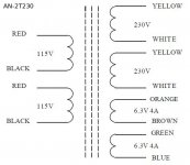
The AN-2T230 is a 200VA transformer with dual 230VAC secondaries, each rated for 400mA of current delivery. Yes, it's a bit over-capacity for the B+ current needs, but it's "just right" for powering the filament-heaters. The 230VAC secondaries will each be bridge-rectified to about 320VDC; placing these rectified power-supplies in a totem-pole configuration will result in a +/-320VDC@400mA power-supply. I believe that the M60 input stage can readily absorb the slightly higher DC potentials (+7%); the tubes are not pushed outside of conservative voltage/current/head-dissipation values. The resistor values in the output-stage fixed-bias voltage-divider will need to adjusted to adapt to the slightly higher DC voltages.
The AN-2T230 power-transformer also provides dual 6.3VAC@4A secondaries for powering the filaments of the four 6SN7 tubes that comprise the input/driver stages. The voltage value is dead-on and the individual 6SN7 filament current needs of 0.6A/tube can be safely and conservatively spread across the two filament secondaries.
The AN-2T230 can be configured for either 115VAC or 230VAC primary voltages.
Power-Supply Transformers: Bridged Output Stages (2x)
-----------------------------------------------------------------------
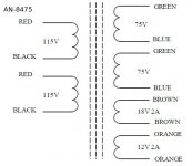
The power-supply transformers for each half of the bridged output stage must provided by separate sets of secondaries; these power-supplies MUST "float" independently of one another. With the available product options, I've targeted a transformer that will provision +/-106VDC power-supplies in order to reduce the 6AS7 plate-dissipation to slightly less than 50% of the rated capacity. The combined peak current draw for each of the output stage power-supplies is 2.5A. The transformer I've targeted for powering the input/driver stage is:
The 75VAC secondaries will each be bridge-rectified to about 106VDC; placing these rectified power-supplies in a totem-pole configuration will result in a +/-106VDC@5.3A power-supply. Two such "floating" power-supplies can power up to an 8-tube 6AS7-based power-amplifier channel.
The auxiliary secondaries are not useful for powering the 6AS7 filaments, so they will be left unused.
The AN-8475 can be configured for either 115VAC or 230VAC primary voltages.
Power-Supply Transformers: 6AS7 Filament Supplies (4x)
-----------------------------------------------------------------------
To power the 6AS7 filaments, four low-voltage/high-current power transformers will be needed.
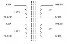
The AN-0506 is an 50VA transformer with dual 6.3VAC secondaries, each rated for 4.2A of current delivery. I've targeted a transformer that will provision two 6.3VAC filament power-supplies for the 6AS7 output tubes; four filament power-supply transformers will be needed in total for each channel (assuming eight 6AS7 output tubes per channel).
The AN-0506 can be configured for either 115VAC or 230VAC primary voltages.
M-60 OTL Power-Supply Transformers (Overview):
-----------------------------------------------------------------------
The original M60 design employs three power supplies for each channel; a +/-300VDC supply, and two "floating" +/-140VDC supplies. The single +/-300VDC supply powers the input stage and the driver stage. The dual +/-140VDC supplies each power one side of the bridged/Circlotron output stage.
If we assume dual secondary power transformers, we need secondary voltage ratings of 212VAC (input/driver stage) and 99VAC (output stages). A search of the usual power-transformer vendors servicing the DIYaudio community illustrated that these secondary voltage ratings tend to fall well outside of the standard product offerings. Fortunately, a buddy who designs custom vacuum-tube instrument/PA gear pointed me to Ango Technology Corporation (AnTek), who manufactures toroidal power transformers with appropriate secondary voltage values; the company's Web site is available at the following URL:
Power-Supply Transformer: Input/Driver Stage (1x)
-----------------------------------------------------------------------
The power-supply transformer for the input/driver stage can provide either center-tapped or separate secondaries since the +/-300VDC power-supplies will be joined at a common reference ground potential. The combined current draw for the input/gain stage and the driver stage is 18mA (with the pumped-up current-source configuration from the MA-1). The transformer I've targeted for powering the input/driver stage is:
The AN-2T230 is a 200VA transformer with dual 230VAC secondaries, each rated for 400mA of current delivery. Yes, it's a bit over-capacity for the B+ current needs, but it's "just right" for powering the filament-heaters. The 230VAC secondaries will each be bridge-rectified to about 320VDC; placing these rectified power-supplies in a totem-pole configuration will result in a +/-320VDC@400mA power-supply. I believe that the M60 input stage can readily absorb the slightly higher DC potentials (+7%); the tubes are not pushed outside of conservative voltage/current/head-dissipation values. The resistor values in the output-stage fixed-bias voltage-divider will need to adjusted to adapt to the slightly higher DC voltages.
NOTE: The effective "center-tap" ground reference will ONLY be attached to the "floating" output-stage power-supplies via the two 600-ohm resistors that bridge the power-amplifier output taps.
The AN-2T230 power-transformer also provides dual 6.3VAC@4A secondaries for powering the filaments of the four 6SN7 tubes that comprise the input/driver stages. The voltage value is dead-on and the individual 6SN7 filament current needs of 0.6A/tube can be safely and conservatively spread across the two filament secondaries.
The AN-2T230 can be configured for either 115VAC or 230VAC primary voltages.
Power-Supply Transformers: Bridged Output Stages (2x)
-----------------------------------------------------------------------
The power-supply transformers for each half of the bridged output stage must provided by separate sets of secondaries; these power-supplies MUST "float" independently of one another. With the available product options, I've targeted a transformer that will provision +/-106VDC power-supplies in order to reduce the 6AS7 plate-dissipation to slightly less than 50% of the rated capacity. The combined peak current draw for each of the output stage power-supplies is 2.5A. The transformer I've targeted for powering the input/driver stage is:
The 75VAC secondaries will each be bridge-rectified to about 106VDC; placing these rectified power-supplies in a totem-pole configuration will result in a +/-106VDC@5.3A power-supply. Two such "floating" power-supplies can power up to an 8-tube 6AS7-based power-amplifier channel.
The auxiliary secondaries are not useful for powering the 6AS7 filaments, so they will be left unused.
The AN-8475 can be configured for either 115VAC or 230VAC primary voltages.
Power-Supply Transformers: 6AS7 Filament Supplies (4x)
-----------------------------------------------------------------------
To power the 6AS7 filaments, four low-voltage/high-current power transformers will be needed.
The AN-0506 is an 50VA transformer with dual 6.3VAC secondaries, each rated for 4.2A of current delivery. I've targeted a transformer that will provision two 6.3VAC filament power-supplies for the 6AS7 output tubes; four filament power-supply transformers will be needed in total for each channel (assuming eight 6AS7 output tubes per channel).
The AN-0506 can be configured for either 115VAC or 230VAC primary voltages.
Attachments
I have a little bit of trouble tracing the M-60 schematic so this may not apply at all.
But going back to the basic circolotron one tube does the positive one does the negative. you can typically place a ganged attenuation circuit on the grids of both stages this will change the volume in the circuit. pots are good for this. If it can handle the power from the driver tube you can use something like the lm13600 which i just found last night when doing research for my own project (an eq).
its a dual transconductance amp (current mirror). depending on how this thing is wired you may need to insert a coupling cap so you dont send B+/B- voltage into it.
I have a little bit of trouble tracing the M-60 schematic so this may not apply at all.
But going back to the basic circolotron one tube does the positive one does the negative. you can typically place a ganged attenuation circuit on the grids of both stages this will change the volume in the circuit. pots are good for this. If it can handle the power from the driver tube you can use something like the lm13600 which i just found last night when doing research for my own project (an eq).
its a dual transconductance amp (current mirror). depending on how this thing is wired you may need to insert a coupling cap so you dont send B+/B- voltage into it.
This is true but you will have to contend with the pot as part of the load that the driver has to drive. So you are better off putting it at the input. We usually use a dual 100K device.
BTW passives have grave difficulties controlling the interconnect cable and so can introduce colorations. The traditional one is less bass/impact at lower volumes. That is why we developed the MP-1, which uses the Circlotron to directly drive a 600 ohm load. You put the 600 ohm load at the input of the amplifier (pins 2 and 3 of the XLR). The result is the old 'audio engineer' adage that 'cables don't affect the sound'. In fact that is the case- if you have a 600 ohm balanced line and a line drive source that can manage it. Quite literally the most expensive/'best' cable in the world will sound no better than a set of inexpensive balanced cables from the guitar/music store. After all, that is what balanced lines were created for- to eliminate the artifact of cables. You would think audiophiles would go for that...
BTW, we do have a little driver power supply transformer that does the job very nicely and it has a good ESS. Its $45.00 each. Normally we run the driver filaments off the power tube filament transformers. 6SN7s can handle a fair amount of filament/cathode voltage and we never have a problem. Otherwise you need to be careful of electrostatic noise coming in through the filament circuit. If its all handled right the amp will be quite on 105 db horns.
I was thinking about the MP-1, I thought I had read that it also used similar topology. Of course I couldn't verify any of it but it sounded reasonable.
I love the simplicity and elegance of the M60 circuit and if the MP-1 is built with the same grace I'm sure it's awsome as well.
Being a n0ob as I am there are still a couple embaressing questions left...
Looking at the schematics.
Where do you connect the Bridge1(+), Bridge2(-), Bridge2(+) and Bridge1(-)?
And, is the +/- 140V connected to the B+(2) and B-(2)?
I feel like such an idiot asking these simple questions, hate being a no0b. But if I don't ask I won't learn anything.
I was thinking about the MP-1, I thought I had read that it also used similar topology. Of course I couldn't verify any of it but it sounded reasonable.
I love the simplicity and elegance of the M60 circuit and if the MP-1 is built with the same grace I'm sure it's awsome as well.
Being a n0ob as I am there are still a couple embaressing questions left...
Looking at the schematics.
Where do you connect the Bridge1(+), Bridge2(-), Bridge2(+) and Bridge1(-)?
And, is the +/- 140V connected to the B+(2) and B-(2)...
MarkusG,
The M-60's fully-symmetric, bridged output stage hides a lot of sophistication in its apparent simplicity, making it difficult to see what's taking place until you can wrap your head around the whole thing. It's important that you clearly understand how the dual "floating" power-supplies for the output stage are integrated into the bridge circuit; let's use the simplified schematic (in which I've labeled the floating power-supplies to correspond to the labeling in the M60 signal-wiring diagram) that I've attached to this post.
The output stage power-supplies (Bridge 1 and Bridge 2) are each comprised of a +140VDC and -140VDC supply, which are stacked to provide a total 280VDC voltage source between the (+) and (-) terminals in the simplified schematic. The "ground" potential between these stacked power-supplies is never exposed or connected to any other point in the M-60. The "Bridge 1" (+) terminal is attached to the plate of V1, but the "Bridge 1" (-) terminal is attached to the cathode of V2. Similarly, the "Bridge 2" (+) terminal is attached to the plate of V2, but the "Bridge 2" (-) terminal is attached to the cathode of V1. "Bridge 1", "Bridge 2", V1 and V2 comprise the four elements of a traditional bridge circuit. In reality, each of V1 and V2 is actually made up of eight parallel triodes (four twin-triode 6AS7G tubes). Each of the power supplies (shown as "Bridge 1" and "Bridge 2") must be fully independent, with its own secondary winding, rectification and smoothing. This is the only real additional complexity of this output stage configuration, as contrasted with a more traditional push-pull output stage.
Since this is a differentially-driven follower circuit, the load (the loudspeaker) is attached between the cathodes of the paralleled output tubes. While the load is essentially attached to the -140VDC terminals of the "floating" power supplies, that voltage potential is un-referenced --- the output-stage power-supplies are "floating" with respect to any "ground" reference.
Under quiescent conditions, the currents I1 and I2 flowing in the two halves of the circuit are identical, so no current flows through the load. Resistors R1 and R2 (they're 600-ohm, high-wattage resistors) tie the two ends of the load to ground and ensure that they are at the same voltage potential. This ground reference is the only means by which the fixed-bias voltage (developed within the independent dual-rail B+/- power-supply for the input/driver stage) can be exerted against the output-stage vacuum-tubes, establishing the quiescent current for the output stage.
Take a moment to let your brain assimilate how the output stage components are interconnected to form a fully-symmetric bridge circuit --- there's a lot to consider. I know it took some time for me before I had that "Ah HA!" moment...
BTW, there's some decent high-level background information on bridge circuits on Wikipeda; here's a good launch-point:
I hope that helps...
Attachments
Last edited:
- Home
- Amplifiers
- Tubes / Valves
- What tubes for a OTL tube amp?