If they were KT88 as you said, you can get about 300W, but think about the output trafo, if you want to go low as 20Hz or lower in high power, you will need a costly and massive 20Kg output transformerYou made a beautiful amp man!
I can't help but to wonder how much power you could get out of 12 tubes per channel with an OPT though... If they were KT88 you'd have over 400W!
 .
.Very Nice!
I mean the 6336B not the 6C33S. Run about 5amps heater current each! Look a bit like the KT88 though!
I am still chasing gauges if you have any inspiration!
Hi,
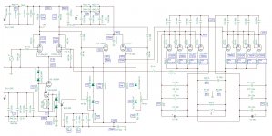
I have planned to build my own 6336A circlotron OTL amp (2 monoblocks), I have got all the parts but I have not yet found the time to build it.
If you are interested I attach the schematic so you can take a look at the driver stage (D3A + 5687).
Andrea
Attachments
Very Nice!
I mean the 6336B not the 6C33S. Run about 5amps heater current each! Look a bit like the KT88 though!
I am still chasing gauges if you have any inspiration!
I got lucky with my meters. They're from the early forties I suspect. Ebay has just about every style of panel meter you could want. Depends on the look you're after. Whatever you decide, I'd put protection diodes across the terminals. I've got some Collins radio stuff from the early fifties which match my amps
I believe no one can tell, unless the designer himself told you what topology he use, IMHO the 90% of the sound "character" of an amp, is due to input and driver stages and depends on the schematic and which tube you use.
I believe no one can tell
I think so too. But you might be able to tell if NFB is engaged or not from bass response.
Miyajima Laboratory {transformer / others}
A look at the photo on their web site shows that the output stage has independent bias adjustment, coupling capacitor for each tube which has some % to the claim below:?
The sound quality of this amplifier clear and powerful.
This amplifier does play music obediently.
The output tubes has different gain and single or parallel do make some differences (more tubes seem to be less sharper, unless you care to do as above co.). I have 1 pair of 6c33c and 5 pairs of 6c19p using same driver, they sound almost the same except 6c33c is sharper and faster. Need a lot tweeting to make sound good, then it will be good for both amp.
Last edited:
Not only from bass response , from high frequencies response too and from low distortions .I think so too. But you might be able to tell if NFB is engaged or not from bass response.
Miyajima Laboratory {transformer / others}
A look at the photo on their web site shows that the output stage has independent bias adjustment, coupling capacitor for each tube which has some % to the claim below:?
The sound quality of this amplifier clear and powerful.
This amplifier does play music obediently.
But looking at the specs of the amp , they say that ... non NFB
10Hz - 100,000Hz (-1dB, 1W, non-NFB)
10Hz - 250,000Hz (-3dB, 1W, non-NFB)
The S/N ratio of this amplifier is very high.
which is very difficult to achive without global NFB .
More output tubes seem to be less sharper as you said because of higher input capacitances , those capacitances together with the output impedance of the previous stage forms a low pass filter which decrease the high frequencies response.The output tubes has different gain and single or parallel do make some differences (more tubes seem to be less sharper, unless you care to do as above co.). I have 1 pair of 6c33c and 5 pairs of 6c19p using same driver, they sound almost the same except 6c33c is sharper and faster. Need a lot tweeting to make sound good, then it will be good for both amp.
..less sharper as you said because of higher input capacitances
Right, 6c33c has a mu of 3, 6c19p mu of 6 and 6080 mu of 1.5, it's not surprising why 6080 has been chosen, since GM in parallel tubes increased and hence the higher input capacitance your mentioned.
I presume the output of Circlotron is always< unity if cathode connected, the overall gain does not increased in parallel tubes. Maybe I have simulated it to make sure.
Oh, beside the mu of 1.5, the actual input capacitance Grid to cathode and heater(6080) is 5.5 pf, there is much difference if the stage has net gain or not (when parallel more tubes GM always increased) as capacitance due to Miller effect would be more in totem pole, esp the bottom tube which is a common cathode stage.
Oh, beside the mu of 1.5, the actual input capacitance Grid to cathode and heater(6080) is 5.5 pf, there is much difference if the stage has net gain or not (when parallel more tubes GM always increased) as capacitance due to Miller effect would be more in totem pole, esp the bottom tube which is a common cathode stage.
Last edited:
I know Miller efect well I said that it will be no great difference because we have mu of 1.5, meaning that this difference will be small compared to a tube with mu of 5 for example , beside this you are making a mistake here, in Futterman topology the two tubes are working as common cathode not only the lower tube, in the inverted Futterman topology (which I use it in my amp), the two tubes are working as cathode followers, that's why we have lower output impedance by using this topology!
I said that it will be no great difference because we have mu of 1.5, meaning that this difference will be small compared to a tube with mu of 5 for example , beside this you are making a mistake here, in Futterman topology the two tubes are working as common cathode not only the lower tube, in the inverted Futterman topology (which I use it in my amp), the two tubes are working as cathode followers, that's why we have lower output impedance by using this topology!
Last edited by a moderator:
One should not rule out because it's small number of tubes, it's the fundamental.
More than 15 years ago I posted an email to Editor of TubeCab about this totem pole and he didn't disagree with me, I believe still on his website. I don't want to high jack this thread, so thank you for your comment.
More than 15 years ago I posted an email to Editor of TubeCab about this totem pole and he didn't disagree with me, I believe still on his website. I don't want to high jack this thread, so thank you for your comment.
Miller capacitance in a cathode coupled amplifier is cgp*(1+A) where A is the actual gain, not u, in a totempole OTL the gain normally is so low that miller effect is very low also. In my 25W OTL amplifier I have about 50V pk grid drive and output Pk is only 20V, (25W in 8 ohm) so gain is about 0.4, thus Miller capacitance is only 1.4 times Cgp, that gives wide bandwidth.
Last edited:
Don't look at the Futterman topology as a totem pole, the two tubes (or even many parallel tubes) are acting as common cathode stages, therfore there is a gain, in the inverted Futterman topology there is no gain because tubes act as cathode follower, read this circlotron-output-impedance.
No one disagree about Miller effect in a cathode coupled amplifier, or Miller effect in general!
No one disagree about Miller effect in a cathode coupled amplifier, or Miller effect in general!
- Home
- Amplifiers
- Tubes / Valves
- What tubes for a OTL tube amp?