So, I have been searching and reading up on the various sources on how to apply small signal pentodes to input stages, and more specifically, how best to treat g2. I am actually pretty unsatisfied with what I have read, since there definitely seems no consensus as to whether to use a single B+ drop resistor, a resistor voltage divider, simple zener + cap, or full blown regulator. I think the main reason for that is using pentodes for anything other than finals is not that popular in DIY, and secondly all the classic texts predate SS. Thoughts?
So, I have been searching and reading up on the various sources on how to apply small signal pentodes to input stages, and more specifically, how best to treat g2... Thoughts?
This is another one of those "it depends" situations. The main thing is to get that screen voltage as low as possible for improvement in linearity. As to how to supply it, a series dropping resistor with cathode bias has the advantage of introducing enough "slop" to compensate for tube aging, characteristic variations across different brands and across different models, the use of "next closest" resistors. If it's a low level stage, there typically won't be enough plate and screen current variation with signal level for it to make much difference.
If the variation is greater, then a single series dropping resistor can introduce an undesirable "variable-u" feature that can increase distortion. In that case, a stiff voltage divider would be better, especially if you have to tie the screen to the cathode for AC. If that's not the case, then Zener regulation is better still.
"I think the main reason for that is using pentodes for anything other than finals is not that popular in DIY..."
Small signal pentodes aren't usually all that useful. If you're doing an amp with the usual 1.0Vrms input, you probably don't need that much gain. For low level sources (phono carts, gee-tah amps) pentodes aren't desirable due to noise considerations. For low level audio amplification, solid state, triodes, cascoded triodes, hybrid cascodes are preferred for better noise performance.
There is also the "laziness" factor. It's easier to design a multi-stage triode gain stage than to use one pentode. With pentodes, you have to play around with screen voltages to minimize distortion.
For RF amplification, it's much easier to use pentodes. At frequencies well above audio, there is much less noise, and all that's necessary is to horse up the plate current, connect to an LC tuner, and rely on the fact that the impedance of the LC plate load will drop considerably at off-resonant frequencies, so there simply is no harmonic distortion to worry about since there won't be any gain at those frequencies.
The above posts are supported.
But 'in the olden days' pentodes have been used quite successfully for low-level inputs. Those guys found them useful, and I cannot imagine they knew less about tubes than today or that the standards were lower.
I do think the noise thing is somewhat overrated. Definitely in power amplifiers I do find an audible difference noise-wise with a pentode input stage only if you put your ear almost inside the loudspeaker. Noise levels of -85dB is quite achievable. Even for RIAA purposes they did duty as input stages.
The advantage is that for low level signals, measurements show that pentode distortion can go down to 20% of that of triodes - fine, that might not be a factor either way. Then there is also the triode Miller-effect thing for a poorly defined, or rather variable input impedance effect. Here the triode-cascode could be a better choice.
But about your real question. Again, my depressing experience is that modern low-signal pentodes can come out with what would have been an unacceptable inconsistency of characteristics before. One could stabilize the supply as Miles said, but to me it would seem to be more compensating with the normal series resistor ... Miles? Then with respect, I would not use a straight zener diode; they are noisy, and at high enough voltage - order of 50 - 80V? - they have a worrying positive temperature co-efficient. With some applications (e.g. feeding a cathode-follower or concertina phase splitter directly), some dc stabilisation is possible by feeding the dc off the respective cathode (it is dc negative feedback). Just realise that the bypass capacitor must then be the G2-µ factor higher in value. Also, stabilization to earth instead of cathode if the cathode is e.g. used for feedback, disarranges the topology. (Pentodes do their thing with constant voltage between cathode and G2.)
But I would say that in small-signal applications matters are not so critical as e.g. with power pentodes. The G2-currents are very low and to my notion not that much influenced by signal amplitude. It is class-A anyway.
Hopefully others will join in.
I have built three power amps with pentode inputs. Two use the 6AU6 and the most recent one a 12L8GT (an unusual low transconductance dual power pentode). Noise is not an issue as far as I am concerned, and my speakers are 100db+ sensitive.
I suppose it depends on your choices.
Shoog
I suppose it depends on your choices.
Shoog
Heard it said that cascoding emulates a pentode - is this comment just about gain or do cascoded triodes have partition noise as well? What tubes and/or mu levels for cascoding would you all recommend in "geetah" amp situations??
Also ...
Miles - can you talk more about this variable-mu and how/why it causes distortion?? 2nd harmonic?? We geetah players like distortion after all .
.
thanks
Also ...
If the variation is greater, then a single series dropping resistor can introduce an undesirable "variable-u" feature that can increase distortion ...
Miles - can you talk more about this variable-mu and how/why it causes distortion?? 2nd harmonic?? We geetah players like distortion after all
.thanks
Use signal pentodes as triodes. Far more predictable results. So of the TV stuff EF184 grouping offer excellent linearity and reasonable gain in such config. As others mentioned, G2 voltage is the stickler when it comes to low distortion, some tubes have 2 voltage points of minima. The obsolete 7199 class is a known one for this, and the unspecified G2 voltage will vary from tube to tube.
richy
richy
According to Ed Cherry:
The screen should be very well decoupled since any impedance there allows a noise voltage to appear at the screen.
Low gm tubes are often less noisy than high gm types (I think the wider grid-cathode spacing results in less grid noise, but I could check that). Yes that one surprised me too!
Lowering the heater voltage slightly will sometimes give improved noise.
There is massive noise variation between samples, so hand-selecting tubes is essential.
Pretty much anything goes for guitar. Having said that, the ECC83 / 12AX7 makes a very poor cascode, although it can be ok at the amp's input. Otherwise the ECC82 / 12AU7 and 6SN7 make good cascodes. Hifi-ers love the ECC88 / 6DJ8, but it's not as suitable for guitar since it's hard to overdrive, very linear (no colouration) and not pin compatible with the ECC83 (so no tube rolling).Heard it said that cascoding emulates a pentode - is this comment just about gain or do cascoded triodes have partition noise as well? What tubes and/or mu levels for cascoding would you all recommend in "geetah" amp situations??
If you look at the anode characteristics of a variable mu pentode you will see that the grid curves are really stretched apart at higher currents and then get progressively squashed together at low currents, so each half of the audio signal will be similarly stretched on one side and squashed on the other. This introduces a lot of 2nd harmonic. For guitar however, the effect probably isn't as obvious as you might hope (probably less than what a DC-coupled cathode follower usually gives you), until you start to OD the valve.Miles - can you talk more about this variable-mu and how/why it causes distortion?? 2nd harmonic?? We geetah players like distortion after all
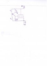
Sorry for the hand drawing.
I use this circuit in the g2 supply of a 13E1 Se.I was recommended this circuit by 7N7, who used it in the g2 supply of a pentode cathodefollower.
Initially I had S130P (pre ww2 vr tube) but it was not performing as well as the other vr tubes in the amplifier( driver tube is pentode with 0c3 in g2 supply, unbypassed cathoderesistor).
The amplifier delivers 32-34 w .
THD 1,2 % at onset of clipping.noise on output with 1 k termination on input, is 400µv.with the 400 hz filter connected around 100µV.
As a newbie many things is unclear.can anyone explain if the cap from collector to ground is needed when b+ is regulated ?
Attachments
Sorry for the hand drawing.
I use this circuit in the g2 supply of a 13E1 Se.
A 13E1 is about as far away from a small signal pentode as you can get; I think they are the size of glass Coke bottles
The resistor to ground is called the cathode bypass cap. It has nothing to do with PS smoothing, as in regulated vs unregulated B+.
Thanks all for the thoughtful and informative replies and keeping the OT somewhat down.
Last edited:
Miles:
"If the variation is greater, then a single series dropping resistor can introduce an undesirable "variable-u" feature that can increase distortion ..."
Moonbird:
"Miles - can you talk more about this variable-mu and how/why it causes distortion?? 2nd harmonic?? We geetah players like distortion after all "
Here are some curves for screen resistor effects:
http://www.diyaudio.com/forums/tubes-valves/160240-suppresor-grid-used-feedback-2.html#post2071328
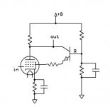
This circuit, presented at ETF2009, is claimed to overcome partition noise. I haven't measured it myself yet...
Very interesting SY. Could you possibly provide more info on the selection of the other component values for a particular pentode?? Thanks for the post.
Miles:
Here are some curves for screen resistor effects:
Uhhh ... WOW whadda thread
.... I think you should be awarded a research grant or something. THANKS for this link!!Why should it do that?
What explanation had been provided for that claim?
This circuit, presented at ETF2009, is claimed to overcome partition noise. I haven't measured it myself yet...
What explanation had been provided for that claim?
"Why should it do that?"
The idea is to return the split off current from the cathode stream (via the screen) back to the plate current. Hence no partition, no noise (ideally). Its more obvious in the Mosfet version I mentioned some years ago, since no current is lost thru the gate, versus some current loss occurs with the bipolar base connection. Don't forget a gate stopper on the Mosfet as well.
The bipolar device may have some advantage as far as lower Z at the screen compared to the Mosfet.
Also, the circuit will need further extensions for a power pentode, where the plate voltage can dip below the screen voltage (and then cutoff collector or drain operating voltage for the screen current bypass device).
This is readily remedied by using a cap from the collector/drain to the tube plate, with a resistor pull-up, or CCS, on the coll./drain (to B+) to keep the DC operating level above the plate.
Another clever approach is to provide a tap on the OT xfmr winding (or a resistor tap, if just resistor loaded) at around 80% of the winding from B+ center, to attach the drain or collector to. This keeps the collector/drain above the plate voltage when it dips below screen voltage.
Last edited:
- Status
- This old topic is closed. If you want to reopen this topic, contact a moderator using the "Report Post" button.
- Home
- Amplifiers
- Tubes / Valves
- Lowering noise in small signal pentodes?