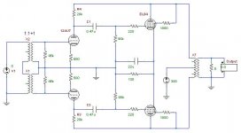
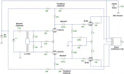
Here is a unity-gain push-pull EL84 power buffer that I'm thinking about.
It uses local feedback from the output tube's plates to the driver tube's plate for unity gain.
The LL1540 input transformer can handle 7.75V input (20dBu) for 0.1% distortion at 50Hz (however, more voltage can be applied with increasing distortion, eventually having 1% distortion at 24V). Using 300V B+, the output stage maximum output is about 12V (peak-to-peak). Therefore, operating the amplifier to full power in unity-gain mode, the input transformer will need to pass 12V p-p, which shouldn't be a problem.
Alternatively, the feedback can include the output transformer's primary by using the UL tap. This gives the buffer a gain of about 2 (determined by the exact location of the UL tap, usually 40%). The means the input only needs 6V p-p drive.
Any comments, suggestions, or critiques?
Attachments
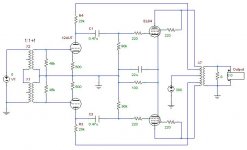
this looks like what im looking for (gain of 2 version). However im confused on the ul tap (round thing with a 300 on it) as to were it goes. Im also confused on size/voltage requirements for hte passives, and what the load of the transformer needs to be (3k 5k?).
Also have you looked at millets 6B4G with 3vrms in? Thats about 8.5vpp.
http://www.pmillett.com/6B4G_push-pull_amp.htm
Also have you looked at millets 6B4G with 3vrms in? Thats about 8.5vpp.
http://www.pmillett.com/6B4G_push-pull_amp.htm
Last edited:
However im confused on the ul tap (round thing with a 300 on it)
It's actually on the center tap of the OPT primary. In a SPICE simulation, it represents a 300V DC power supply. That's your B+.
2V/V (6dB) when connected directly to EL84 plates.
This means operating the output valves in triode mode, which will lower output impedance at a penalty of lower maximum output power.
load of the transformer needs to be (3k 5k?).
You'll want higher impedance, in the neighborhood of 7k to 8k.
I haven't actually tried it out yet. I have the circuit built, but haven't applied power to it and listened. I'm curious if the feedback mechanism of connecting the driver's plates to the output's plates is actually feasible.
I'm curious if the feedback mechanism of connecting the driver's plates to the output's plates is actually feasible.
Yes, the so called plate to plate, which is actually plate to grid, connection works. Refer to the RH84 schematic. An interesting variation on the theme is Bandersnatch's "exolinear" setup.
Attachments
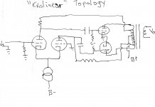
An interesting variation on the theme is Bandersnatch's "exolinear" setup.
If you look at the second picture attached to the OP, is this "exolinear"? (driver plates connected to UL taps).
If you look at the second picture attached to the OP, is this "exolinear"? (driver plates connected to UL taps).
Yes, it is.
BTW, get rid of the 12AU7. It's non-linear.
 You should be able to use the same passive parts with a tube from the 6FQ7/6CG7/12BH7/6GU7 group.
Refer to the RH84 schematic. An interesting variation on the theme is Bandersnatch's "exolinear" setup.
Probably the most extensive exploration of the plate-to-grid feedback in a PP amp is Baby Huey (which was developed based on an ECL86 amp by Yves). Both are here on this forum.
dave
Pardon my ignorance. What are some advantages of using PP in a buffer. Is it less distortion? More linear?
More power. I need it, even with my 92dB/watt/m speakers.
BTW, get rid of the 12AU7. It's non-linear.
Yea, yea. I know. I love the 6CG7, although I can't comment on the 12BH7. I'll buy some and toss the 12AU7. I'll have to swap some pieces (cathode resistor, plate resistor) to get the curves right.
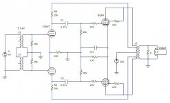
However, in this "exoliner" setup, the dominant tube is the output tube (EL84).
Probably the most extensive exploration of the plate-to-grid feedback in a PP amp is Baby Huey.
Thanks for the reference.
I have the amplifier running right now using 12ATU on the driver and EL84 on the output, using Edcor 8k transformers and about 290V B+. It could handle a bit more B+. I'm running the 12AT7's plate from the UL tap, so the transformer is included in the feedback loop.
You can see on the schematic where the 12AU7's plate can be partially connected straight to B+ and partially to the UL tap. This way, the amount of feedback can be controlled. I just took out the resistor going to B+, so it operates fully in exolinear mode. I also put pads on the circuit board to choose the desired configuration.
Attachments
- Status
- This old topic is closed. If you want to reopen this topic, contact a moderator using the "Report Post" button.
- Home
- Amplifiers
- Tubes / Valves
- Unity-Gain EL84 Push-Pull Power Buffer