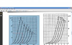
I put 220 ohms on the CCS bias. (couldn't find a 200).
Now I've got better results with the 6N1P.
Plate V: ~170v
B+: 225 v
current across CCS (2/220): 9.1 mA. Not going to burn out the 1w DN2540 with this no?
Do these figures look reasonable?
Thanks very much guys.
Update: music test sounds superb now. no distortion, just sweet tunes.
BUT the dn2540s are getting damn hot, almost too hot too tough. I switched it off as I think they will burn out.
I think I willl switch back to my pentode CCS until I get some 15 watt DN2540s.
You are dissipating 0.5 watts, so you're okay. 55 volts across the CCS x 9.1mA. Don't increase dissipation any more. Make sure air is relatively cool and flowing freely around the MOSFETs.
As SY said, to reduce gain change tubes. 6CG7/6FQ7 is 9-pin equivalent to 6SN7, mu of 20.5, cuts your gain in half. With LED bias and a CCS your stage gain will equal mu.
The 6CG7 likes 150V and 7mA, which can be achieved with 3.4V on the cathode; two red LEDs or four SiC Schottkies.
When you increase your 200R to 220, you'll possibly come pretty close to 7mA, but your B+ will rise as your plate voltage falls. Dissipation will be around 0.6 watts, so get those TO220 cases in the loop.
You're doing well!
Stuart
Try a red LED (~1.7V) and see what you get. An IR LED should get you 1.2V, that may be too low, but worth a shot.
Can I use an LED across the CCS DN2540 to set the bias instead of the resistor or would it just blow due to the 120V?
From the source to the gate?
Or is the LED not seeing the HV, just setting the constant current?
6 x 2N6520
8 x 2N3906
i have these.
can i use these? cascode arrangement?
Remember, thermal management is as important as electrical parameters.
I see that 2N6520 is T0-92 package.
now if you sketch the schematics and calculate power dissipation levels, you will be in the range of several hundred milliwatts. I prefer cases where you can use heatsinks easily.
J
The parameters for Bi CCS are better then that of FET CSS, especially compliane range.
Did you see the performance data for the DN2540 cascode CCS that Walt Jung published?
Did you see the performance data for the DN2540 cascode CCS that Walt Jung published?
yes I did. very impressive. I do not say that FET CCS is bad. What I believe is that them to shine you neet to apply quite a voltage across. With Pimm CCS I needed at least 35-40V for the unit to work as CCS. Similar with Cascoded IXCS.
With cascoded bipolar CCS you are down to several volts (1.8-2V in an extreme).
Cascode CCS with depletion mode MOSFETs vs. C4S with PNPs was no contest in a modified Bottlehead Seduction. The MOSFET current source sounded better. YMMV.
Brit01: as SY said, use a resistor to set the MOSFET CCS current. These things vary a bit, and to set the current you want/need you'll need to tweak a bit. To measure the current through the tube with a SS bias device (or grounded cathode and battery bias) simply measure the voltage across your resistor in the CCS. You must measure the resistance of the resistor itself of course, when you're using a pot. Ohm's law.
Use a 500R pot, see if you can adjust to the current you want with that. Otherwise, you may have to play around a bit to get the value you want. I'd use a good multi-turn pot and leave it in. When you change tubes, you can adjust the pot to experiment with operating points a bit.
Hope this helps.
Stuart
- Status
- This old topic is closed. If you want to reopen this topic, contact a moderator using the "Report Post" button.
- Home
- Amplifiers
- Tubes / Valves
- Which SS CCS for the plate load on a 6N1P?

