As I ponder different feedback methods, another one has popped up. I have not searched so if this has been covered, my apologies.
In our general avoidance of pentodes, we may be missing a better way to introduce feedback through the "other" linear element. The Supressor Grid as used in a true pentode like an EL34. G3 was used for AVC in the past as an easier and more linear way to introduce compression than using other methods. Supressor grid modulation was used in some AM transmitters. It has been mentioned that the screen grid is less than linear for introducing feedback.
I have seen an EF86 used with G3 RC connected to an audio amp for supressor grid modulation.
Could this be used as a linear way to use the UL feedback tap? This grid may use RC coupling instead of a direct UL connection. Could some other feedback loop be used to better advantage than the more commonly seen ones? Plate to g3 without the need for a high gm driver or input transformer as in plate to g1? Voltage feedback from a pot across the output transformer primary, giving a variable % feedback?
I have not thought these through, just tossing out suggestions. The more knowledgable and experienced of you think way faster than I do.
I'll just re-post my comments from the "New? Local Feedback Method" thread:
The coarsely spaced suppressor grid has next to no control effect in most tubes except holding down secondary emission.
"Dual control" pentodes have a fine mesh g3 that can be used for control, but typically has only around a gm of 500 or so. Take a look at 6LE8 or 6BV11, 6GY6, 6HZ6, 6AS6, 6DB6, 6DT6 data sheets. Also, some curves here:
http://www.diyaudio.com/forums/tubes-valves/159892-nice-triode-5.html
http://scottbecker.net/tube/sheets/135/6/6LE8.pdf
g3 modulation works by deflecting plate current back to the g2 grid. This may not be very linear due to the electron velocity spread from passing earlier grids on the way. I will try this on the curve tracer to see. In any case, g2 gets rather hot when a lot of plate current gets bounced back to it.
Last edited:
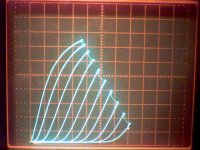
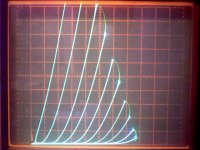
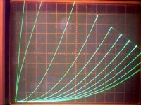
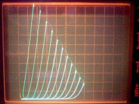
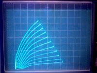
Here is the 9KC6 dual control tube, with g3 acting as control grid on the curve tracer. g2 was at +130 V. g1 at 0V. Horiz. scale 50 V /div. and vertical scale at 5 mA / div. Looks like a LOT of odd harmonic distortion using g3.
Looks great for a vari-mu compressor, not so much for hifi

Guitar effects tube maybe. Take a look at the 6LE8 datasheet too, it has g3 control curves shownon it.
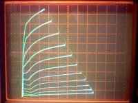
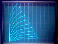
Now here are some 9KC6 g2 control curves,
followed by 6LE8 g2 control curves,
followed by 6LE8 g3 control curves.
The last g3 set are a real surprise. OMG, they look GREAT. We have to keep this to ourselves! Shhh! Secret!
Now here are some 9KC6 g2 control curves,
followed by 6LE8 g2 control curves,
followed by 6LE8 g3 control curves.
The last g3 set are a real surprise. OMG, they look GREAT. We have to keep this to ourselves! Shhh! Secret!
Attachments
Re: Wavebourn
6BA6, sorry, don't have that one. Trying to think of any remote cutoff ones I do have, only 6HQ5 triode I think, which won't help. You want to mail one over? My guess would be that it's quite linear on g2, but with rather reduced gm.
The GE datasheet here:
http://scottbecker.net/tube/sheets/093/6/6BA6.pdf
I don't see any graph there that would give an obvious view or hint between g2 and plate. Top of page 4, vertical line, gives a relation I guess. Can calc the gm2 at least.
"Do you have an EL34, EF86, SV83? "
No, sorry. I have mainly TV tubes, nothing much audio except 6L6, 12AT7, 6CG7/6FQ7, 6SN7, 6BQ5/29GK6/EL84, 12AX7, 12AU7, 5687, 6DJ8.
Some of those should have good data sheets available with g2 plots. Not likely to be much g3 effect with non "dual control" tubes. I tried some horiz. output tubes, and g3 does flat nothing. 29GK6/6BQ5/EL84 shows just a little subtle change around the knees with +30V on g3.
You have mail.
Hi Don;
I'm shipping you now 6BA6, GU-50, 12L6, and some exotic tubes. No need to return, enjoy them after torturing!
RE: Wavebourn
Got the tubes today, arrived in good condition.
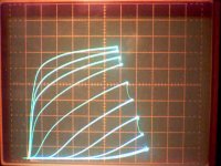
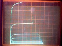
1st tube up for torture: 5763
Axis: 5 mA/ div vertical and 50V /div horiz.
1st plot is with g2 at 140V and g3 at 0V, 1V steps on g1
2nd plot is with g2 at 140V and g3 at -250V, 1V steps on g1
3rd plot is triode mode, 1.9V steps on g1
Seems that the g3 is not effective enough in this tube since -250 V on g3 fixes it up. Seems to be a bit of osc. near the knees too when g3 is 0. Changing g3 voltage in triode mode had almost no effect.
Step size here is rough yet, I still have to do some calibration work on the curve tracer, plus I added a cont. variable control to the step amplifier gain.
I will also have to increase the power supply voltage for the step generator amplifier before I can test the GU-50 fully, I think. Only have around 60V max available at the moment. The step amplifier is already modded for up to 250V.
Got the tubes today, arrived in good condition.
1st tube up for torture: 5763
Axis: 5 mA/ div vertical and 50V /div horiz.
1st plot is with g2 at 140V and g3 at 0V, 1V steps on g1
2nd plot is with g2 at 140V and g3 at -250V, 1V steps on g1
3rd plot is triode mode, 1.9V steps on g1
Seems that the g3 is not effective enough in this tube since -250 V on g3 fixes it up. Seems to be a bit of osc. near the knees too when g3 is 0. Changing g3 voltage in triode mode had almost no effect.
Step size here is rough yet, I still have to do some calibration work on the curve tracer, plus I added a cont. variable control to the step amplifier gain.
I will also have to increase the power supply voltage for the step generator amplifier before I can test the GU-50 fully, I think. Only have around 60V max available at the moment. The step amplifier is already modded for up to 250V.
Attachments
Last edited:
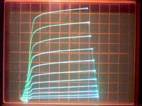
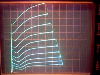
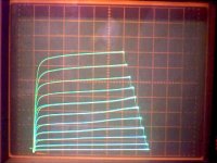
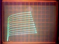
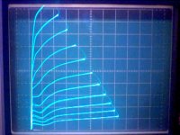
Next tube up: 6BA6W/5749
Plot1: 2mA/div vert. , 50V/div horiz.
100V on g2, 0V on g3, 1.8V steps on g1
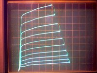
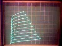
Plot2: 1 mA/div vert. , 50V/div horiz.
0V on g1, 0 V on g3, 5.5 V steps on g2
Plot3: 2 mA/div vert., 50V/div horiz.
1 V on g1, 0 V on g3, 5.5 V steps on g2
Plot4: 2 mA/div vert., 50 V/div horiz.
2 V on g1, 0 V on g3, 5.5 V steps on g2
Plot5: triode config. 2 mA/div horiz., 20 V/div horiz.
2.75 V steps on g1
g3 voltage does have noticeable effects on the knee type plots, +2V squares them up a little tiny bit, over +2 V or minus V rounds them off.
Plot 4 is showing some hum effects from the Tracer power supply I think, comes and goes, need to do some work on the power supplies. Every other trace is from leading or falling 60Hz power sweep, so supply hum crowds every two traces together a little. With 9 traces setup, this alternates between sweeps as to which sets of traces crowd together some.
I wonder if the strange waves in the g2 drive plots are caused by the g1 weird spacing affecting g2 gm locally.
Plot1: 2mA/div vert. , 50V/div horiz.
100V on g2, 0V on g3, 1.8V steps on g1
Plot2: 1 mA/div vert. , 50V/div horiz.
0V on g1, 0 V on g3, 5.5 V steps on g2
Plot3: 2 mA/div vert., 50V/div horiz.
1 V on g1, 0 V on g3, 5.5 V steps on g2
Plot4: 2 mA/div vert., 50 V/div horiz.
2 V on g1, 0 V on g3, 5.5 V steps on g2
Plot5: triode config. 2 mA/div horiz., 20 V/div horiz.
2.75 V steps on g1
g3 voltage does have noticeable effects on the knee type plots, +2V squares them up a little tiny bit, over +2 V or minus V rounds them off.
Plot 4 is showing some hum effects from the Tracer power supply I think, comes and goes, need to do some work on the power supplies. Every other trace is from leading or falling 60Hz power sweep, so supply hum crowds every two traces together a little. With 9 traces setup, this alternates between sweeps as to which sets of traces crowd together some.
I wonder if the strange waves in the g2 drive plots are caused by the g1 weird spacing affecting g2 gm locally.
Attachments
Last edited:
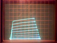
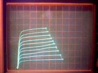
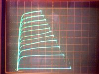
next up, 12L6
Plot 1, pentode: 10 mA/div vert., 50 V/div horiz.
g2 at 95V, g1 1.4V per step
Plot 2, triode: 10 mA/div vert., 50 V/div. horiz.
5.5 V per step on g1
Plot3, g2 drive: 10 mA/div vert., 50 V/div. horiz.
5.5V per step on g2, g1 at +4V
Nice triode.
Plot 1, pentode: 10 mA/div vert., 50 V/div horiz.
g2 at 95V, g1 1.4V per step
Plot 2, triode: 10 mA/div vert., 50 V/div. horiz.
5.5 V per step on g1
Plot3, g2 drive: 10 mA/div vert., 50 V/div. horiz.
5.5V per step on g2, g1 at +4V
Nice triode.
Attachments
"With three grids to play with curves can be altered to make "poor" tubes look good and vicey versy. "
Some other tricks:
12L6 with resistor in g2 circuit. All plots 10 mA/div vert. and 50 V/div horiz., 1.4 v per step on g1, 105V g2 supply
Plot1: no g2 resistor
Plot2: 1.3K Ohm g2 resistor
Plot3: 10K Ohm g2 resistor
Some other tricks:
12L6 with resistor in g2 circuit. All plots 10 mA/div vert. and 50 V/div horiz., 1.4 v per step on g1, 105V g2 supply
Plot1: no g2 resistor
Plot2: 1.3K Ohm g2 resistor
Plot3: 10K Ohm g2 resistor
Attachments
- Status
- This old topic is closed. If you want to reopen this topic, contact a moderator using the "Report Post" button.
- Home
- Amplifiers
- Tubes / Valves
- Suppresor Grid used for Feedback?