Thats the manufacturer I am currently using - but I wouldn't say that those transformers would be usable in this application.
I am using a 600 Ohm input splitter so this type can be used.
These might be worth a punt;
http://cgi.ebay.ca/2-NOS-Audio-Inpu...pt=Vintage_Electronics_R2&hash=item2307d6ae9a
They look like they have a split secondary. Unfortunately the bloke doesn't know enough to describe the ratios - but their cheap.
A bit more expensive - but top quality;
http://cgi.ebay.ca/Lundahl-ll1540-Audio-Input-Transformer-1540-10K-10K-/190402473
Shoog
Last edited:
Output transformer choice
Trawling ebay I found one vendor(Antek) offering dual primary with dual 16v secondary rated at 200VA. There is also another one rated at 300Va. I remember reading somewhere that higher VA transformers affect HF performance.Is it really an issue? Which rating would be the preferred choice with 6336 tubes for output? By the way my speakers are 8 ohm rated.
Thanks for your earlier posts re operating points with 6336 tubes. I think I will go with 130V and higher current as I have a surplus step-down transformer (local 230V to 115V) which could be used this voltage. I will cascode the 317 regulator with a mosfet for reduced heat dissipation and of course attached to a substantial het-sink.
High frequency roll off is a product of interwinding capacitance which is high in power transformers. However I have found it to be insignificant in my implementations and I believed Nelson Pass used a 800VA toroidal in one of his designs.
So I wouldn't worry and go for the 300VA one.
Calculation for impedance is;
Unloaded voltage ratio (ie 230v/18V = 12.7)
square of ratio 12.7^2=162
162 * speaker impedance = 1300 ohms plate to plate load.
Thats how you do it so you can calculate any transformer now.
Br Cornelius
So I wouldn't worry and go for the 300VA one.
Calculation for impedance is;
Unloaded voltage ratio (ie 230v/18V = 12.7)
square of ratio 12.7^2=162
162 * speaker impedance = 1300 ohms plate to plate load.
Thats how you do it so you can calculate any transformer now.
Br Cornelius
Last edited:
I originally looked at using the 6BN11, but couldn't get any compactrons over here in Europe. The transconductance is considerably higher, but that just means more gain so you can use a cheaper step[ down transformer at the input (a mini power toroidal when used in step down mode). The curves don't look as good - but that should be compensated for by the tail CCS on the input. So yes I would say it will substitute.
Shoog
Shoog
Hi, does the 6BN11 suitable for this Schade Amp with good sound? They are quite easy to get on eBay but not the 12L8GT.
I did a 2 stage 6BN11/6as7 before. It works quite well to drive the 6as7 and is probably the coolest looking small tube. I think it would probably work well implemented into Shoog's design with some minor alterations.
One thing I have found with the 6BN11, is that when you tie the screen grids and cathodes directly together all of the mis-match between the two pentodes shows up as Vdc imbalance between the plates. The typical mis-match was significant in the samples I tested. It may not be a bad idea to implement some kind of DC balance mechanism for the driver stage.
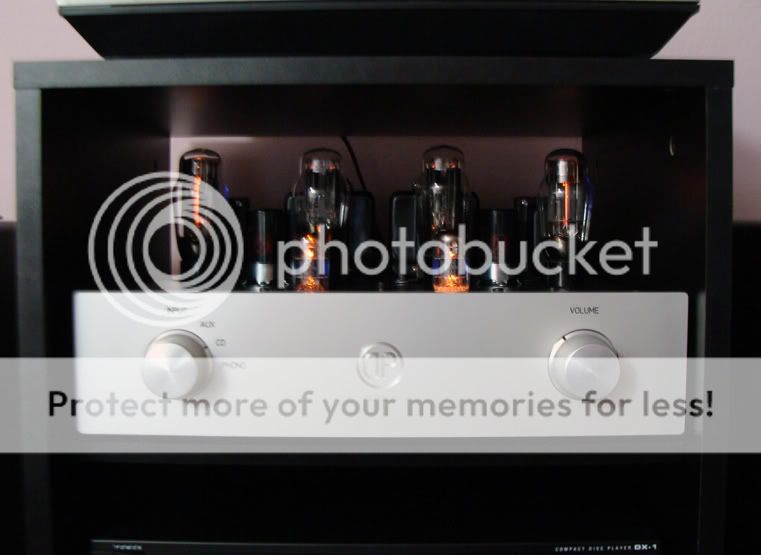
The other thing I can't help but wonder is if the design can be altered to safely run off rectified mains and still perform. Both the input and outputs are isolated by transformers and the voltages pictured are fairly close to what north American mains voltage comes out to when rectified. If you earth grounded the input transformer primary, the chassis, OPT secondary and have NO externally accessible test points, it should provide adequate protection for the "during use" condition. However you would defiantly want to plug the amp into a bench top 1:1 isolation power transformer or isolated variac when servicing the amplifier.
6BN11 + 6as7 amp (the other tubes are rectifiers)
Last edited:
From Mk l to Mk ll
Steve,
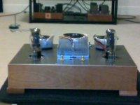
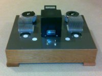
Attached is the 'MK l' I completed couple years back and this is the one that some of my friend didn't want to give me back for quite a while. I end up finished one exactly the same for one of them and now I'm going to discard this 'Mk l' into a 'Mk ll'. Output transformers will keep the same, but the PTXs will be 2 other transformers which I won from the auction lately from feebay. Will post a new amp in about a week, just how it's look and will start after that, for I'm still waiting for some parts to come.
I'm considering to cascode the DN2540 for the driver, but still struggling on how big the resistor to control the current 16mA. My intention is to put a fix 47 ohm 1/2 w to series a 50 ohm 1/2 trimmer so to tightly adjust the plate to 0. Is that numbers are on the ballpark.
For the output connection, I had my last one hooked up 115-0-115 as primary and parallel 2x 9v as secondary/output. As of Mk ll schematic, you said 220v/10v for 4 ohm and 18v for 8 ohm. Do I have to series the secondary to 18v for the Mk ll / or just keep the same ??
BR
Albert
Steve,
Attached is the 'MK l' I completed couple years back and this is the one that some of my friend didn't want to give me back for quite a while. I end up finished one exactly the same for one of them and now I'm going to discard this 'Mk l' into a 'Mk ll'. Output transformers will keep the same, but the PTXs will be 2 other transformers which I won from the auction lately from feebay. Will post a new amp in about a week, just how it's look and will start after that, for I'm still waiting for some parts to come.
I'm considering to cascode the DN2540 for the driver, but still struggling on how big the resistor to control the current 16mA. My intention is to put a fix 47 ohm 1/2 w to series a 50 ohm 1/2 trimmer so to tightly adjust the plate to 0. Is that numbers are on the ballpark.
For the output connection, I had my last one hooked up 115-0-115 as primary and parallel 2x 9v as secondary/output. As of Mk ll schematic, you said 220v/10v for 4 ohm and 18v for 8 ohm. Do I have to series the secondary to 18v for the Mk ll / or just keep the same ??
BR
Albert
Attachments
")
- Status
- This old topic is closed. If you want to reopen this topic, contact a moderator using the "Report Post" button.
- Home
- Amplifiers
- Tubes / Valves
- DC7 MkII :New Schade 6080 amp.