Is there a simple test procedure for determining the frequency response of audio transformers? I have a couple of decent waveform and signal generators, as well as accurate DMMs and a Tektronix 453 scope with good probes. Is this enough to do the job?
I'm asking because I was given a dozen UTC PA-5666 audio interstage transformers. I've been unsuccessful trying to dig up any specs on them. (They're also stamped H83106-01 on the top of the can). They're little; about the same size as the RA-25 or the "Ouncer" series. They're a single 15K winding primary which splits into a dual 95K secondary.
The old UTC catalogs show several transformers with the same specs and approximate dimensions, but with very different performance. The O-6 and 0-7 are 1 dB down at 30 - 20K Hz, but the H-6 is +/- 2 dB from 200 - 10K. Obviously, I'm hoping these little units perform more like the O-6s than the H-6s.
Recommendations on how to proceed?
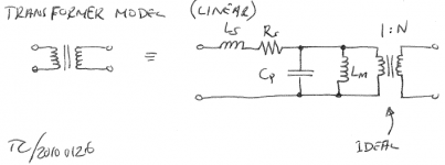
A linear transformer model is shown below. This model gives a pretty accurate frequency response and can be used to simulate stability of an amplifier. But it does not include the effects of transformer saturation, etc., hence, won't give accurate results if you try to simulate distortion. But I find that unless I drive the transformer near saturation, the model works reasonably well.
You measure the parameters as follows:
The turns ratio N is measured by applying an AC voltage to the primary and measuring the secondary voltage. N is then Vsec/Vpri.
Ls, Rs can be measured by shorting the secondary winding and measuring the impedance of the primary winding at frequencies below the resonance frequency. Ls can be calculated from the imaginary part of the impedance, Rs from the real part.
With the secondary floating, measure the impedance of the primary below the resonance frequency. The magnetizing inductance, Lm, can be calculated from this impedance. Subtract Ls from the calculated inductance to find Lm. In most cases, Lm is a few orders of magnitude greater than Ls, so one may argue that the subtraction isn't really necessary...
Once the inductances are known, Cp can be calculated from measurements of the series and parallel resonance frequencies.
I usually use an HP 4194 Gain-Phase/Impedance Analyzer for these measurements -- mostly because I have access to one and it can do all the math to calculate the equivalent circuit components from an impedance sweep. A network analyzer would be an excellent tool for the job as well. It'll be a bit trickier and probably not as accurate to measure these parameters with an oscilloscope, but it should be possible. All you need is the ability to measure current and voltage versus frequency. I'm pretty sure I've seen people make impedance analyzers out of a PC with a sound card. If you don't want to design your own circuit, that could be an option...
I've used the linearized model for both audio design and switchmode power supply design. It works pretty well...
~Tom
Attachments
- Status
- This old topic is closed. If you want to reopen this topic, contact a moderator using the "Report Post" button.