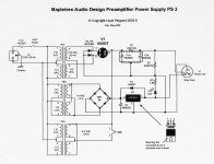
I purchased a Maple Tree Audio preamp a while back. It comes with the Line SA SE pre and the PS 2 power supply. Right out of the box I couldn't help but notice audible hum coming though the pre. When I say audible I mean audible even in low volume passages of music. For me this much hum is unacceptable. I did contact Lloyd and then send the unit back to him to check it. He sent it back saying he had tested it, that it had checked out, and that he had tested the hum level as well and that it was at an acceptable level, well maybe for him.
I haven't been using this unit because of the hum issue so I'm wondering if I can perhaps improve on the PS to get rid of the hum. What I'm wondering is if I can put in a choke in place of the 6.8K R1. Just wondering how many Henries I would need as well as what resistance on the choke and if I can make up the difference in resistance with a 5W resister?
Thanks
Lar
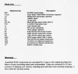
Attachments
In this case, you don't care about the choke's DCR. You will add a resistor after the choke to make the total = the 6.8 KOhms in the schematic.
The power trafo is good for but 25 mA. So, a large inductance is highly feasible. The 595 Ω DCR/40 mA. rated/40 H. Hammond 157G will put a serious dent in the ripple level.
BTW, you said hum, not buzz. Hum at the mains frequency could be caused by a grounding scheme defect, in the signal circuitry. Look into that possibility, before spending on the choke.
Thanks Eli!
I did check it fairly thoroughly before I sent it back to Lloyd at Maple Tree and again when I got it back and it was still humming. Maybe temporarily replacing one leg of the 100/100 JJ with a motorrun might tell me what I need to know. Actually I have a humongous 100uF 750V Electronic Concepts Metalized Poly that will do the trick. If that gets rid of the hum the choke should do it as well, .
.
Cheers
Lar
I did check it fairly thoroughly before I sent it back to Lloyd at Maple Tree and again when I got it back and it was still humming. Maybe temporarily replacing one leg of the 100/100 JJ with a motorrun might tell me what I need to know. Actually I have a humongous 100uF 750V Electronic Concepts Metalized Poly that will do the trick. If that gets rid of the hum the choke should do it as well,
.Cheers
Lar
Hi Lar ,
That is a bad design for a power supply .
The hybrid bridge rectifier is OK , BUT a 6X5 GT , feeding
a 100 uf filter cap is very abusive .
As you know , at EACH half-cycle , the current flows through
ONE diode and ONE plate-cathode path of the 6X5GT .
The capacitor does not charge slowly and smoothly . It charges through
high intensity pulses of current , that necessarily flows into
the tube rectifier ( plate-cathode path ) and one diode , as
described above .
The diode is OK , no problem with it , because it can handle
the peak of current pulse , BUT the 6X5 GT , DOES NOT , thus
the tube is a big obstacle in the current pulse’s path . The
capacitor does not reach the total charge , then the P.S. gets a quick
and progressive increase in the ripple’s level ( translated in
a high level of “ hum “ noise )
As it is , this power supply will not be silent and “ hum “ free .
IMO , the solution is : replace the tube rectifier with a pair of
diodes ( the same already used ) , obviously the output voltage
will rise , because there is no longer a tube in the path , then
add a new RC network , to lower the voltage at the correct value .
The additional cap can be another 100 uf x 500 V , and the resistor
must be calculated using the Ohm’s law , depending on the current
consumption of your preamplifier , and the voltage amount that you
have to lower , as follows :
R ( ohm ) = Voltage amount that need to be lower ( Volts )
Preamp current consumption ( Ampere )
Because the very quick raise on the voltage level ( there is no longer
a tube in the path , that needs to be heated ) , it is advisable to connect
a separated power switch for TR1 ( stand-by switch ) to avoid cathode
stripper .
Regards ,
Carlos
Carlos,
I agree that the design is quite questionable. Apparently, the low current capability of the rectifier winding and the resistance of the rectifier winding are preventing arcing over.
IMO, the "best" way to deal with the lower forward drop in SS diodes is to keep the 1st cap. of a CLC filter small and pile the energy storage up in the 2nd cap. position. The comparatively large conduction angle associated with a small 1st cap. reduces the amount of overtone energy in the ripple waveform. That reduction lowers the possibility of "hash" sneaking into the rail, via the capacitance of the choke.
At the approx. 150 V. this PSU produces, cathode stripping is a non-issue. Also, a cLC filter has an automatic soft start, courtesy of the time constant formed by the choke's DCR and the large amount of 2nd position capacitance.
Snub the existing fast diodes with high WVDC 10 nF. caps. and substitute a MBR20200CT for the 6X5. Parallel the 2X 100 μF. sections for the 2nd position, replace the 6.8 KOhm resistor with the Hammond 157G, and start with 4.7 μF. in the 1st position. Add capacitance to the 1st position until the rail voltage is where it should be.
Hello Carlos,
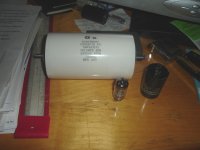
I have some very nice high quality CDE metalized polys. 30uF 600V and 35uF 550V. If I were to put one of these in place of the first 100uF section would that solve the charging issue? Would I need to change the value of R1?
Here's a pic of one of the 30 uF CDEs beside the huge 100uF EC poly with a 12AU7 for perspective.
I've used these CDEs after rectifier tubes before and they perform well.
Cheers
Larry
Attachments
Hello Eli,
Must have been posting as you answered Carlos.
I would still need to make up for the lost resistance of taking out the 6.8K R1 correct? So I'm wondering if I could use one of my CDE 30uF caps in the first position, the Hammond 157G in place of the 6.8K resistor, use a 220uF 500V Panasonic in the second position and then vary the value of the added resistor after the Hammond choke to adjust the rail voltage till it is correct.
Cheers
Lar
Just wondering if I could get away with using a 154E choke instead? The size would be more suitable for the chassis.
Also in this situation does it matter if the resistor making up the resistance for the replaced 6.8K comes before or after the choke,
Thanks, appreciate your guys help!
Lar
Also in this situation does it matter if the resistor making up the resistance for the replaced 6.8K comes before or after the choke,
Thanks, appreciate your guys help!
Lar
Lar,
I have the Maplewood line preamp and listen to it every day. No hum whatsoever. I am not an expert on electronics but you might post the rest of the schematic as there is another 100 uf electrolytic cap in the power supply stream that is inside the other enclosure (i swapped it out for a homemade multi-parallel mpk that sits on top of the unit-ugly but sounds better IMHO). Funny Lloyd said it checked out-could you have an incompatible source?
regards
dave
Thanks Eli!
I did check it fairly thoroughly before I sent it back to Lloyd at Maple Tree and again when I got it back and it was still humming. Maybe temporarily replacing one leg of the 100/100 JJ with a motorrun might tell me what I need to know. Actually I have a humongous 100uF 750V Electronic Concepts Metalized Poly that will do the trick. If that gets rid of the hum the choke should do it as well,
Cheers
Lar
You're suppose top chase down the issue rather than hack the unit to pieces ! What level of B+ ripple is present ? What amount of hum/buzz do you measure at the output jacks ? What is the frequency 60 or 120Hz . What about with source/amp connected or disconnected ?
316a
You're suppose top chase down the issue rather than hack the unit to pieces ! What level of B+ ripple is present ? What amount of hum/buzz do you measure at the output jacks ? What is the frequency 60 or 120Hz . What about with source/amp connected or disconnected ?
316a
I wasn't suggesting that I install the humongous cap but simply put it into the circuit temporarily ;^). Good way to trouble shoot in my experience.
Cheers
Lar
Lar,
I have the Maplewood line preamp and listen to it every day. No hum whatsoever. I am not an expert on electronics but you might post the rest of the schematic as there is another 100 uf electrolytic cap in the power supply stream that is inside the other enclosure (i swapped it out for a homemade multi-parallel mpk that sits on top of the unit-ugly but sounds better IMHO). Funny Lloyd said it checked out-could you have an incompatible source?
regards
dave
Hi Dave,
I tried a variety of sources with it. Even tried using my Tercel phono stage with it with the same results.
I'll do a scan of the other schematic and put it up.
Cheers
Lar
Hi Eli , Hi Lar , sorry for the delayed reply .
Yes , I agree .
Yes !! Fortunately . But I think that is not the only drawback in this design .
The Sylvania Technical Manual 12th edition ( 1958/59 ,I'm not sure ) says that the 6X5 GT ( electrically similar to type 6X4 ) ,connected in a capacitor input filter , does not may have the 1st cap , larger than 10 uF , and to have minimum effective impedance per plate of 525 ohms . As you can see it is a tube with a very limited capacity , and must be used with certain care .
This tube has a bad percentage of regulation , < 15 % .
Another thing that I do not agree ( IMO ) is the use of a 6K8 x 5W + 100 uF , not a good choice .
We can get BEST results , if spliting the 6K8 x 5W + 100 uF RC network , in 2 or 3 parts : 2 or 3 RC networks with 2K2 x 5W + 30/35 uF ( or even 50 uF ) one after another , being the 1st cap a 10 uf MKP unit .
( The Scroggie table ) .
I do not know , if you ( Lar and Eli ) are going to agree with me , but I have
two suggestions for this power supply :
1 ) Let the rectification stage stays as it is ( 6X5 GT + diodes ) , then a 1st
cap of 10 uF , then a filter choke as described above ( need to know the
coil DCR , to subtract it from the 6K8 ohms total resistance ) , then a 2nd
cap of 100 uF , then 2 or 3 RC networks , composed by +/- 2K2 x 5W +
30/35 uF ( or bigger , if available )
The total resistance R1 + R2 + R3 + Choke DCR must be equal to 6,800
ohms , to give the same voltage value at the output .
This is my favorite solution .
2 ) Replace the tube with DIODES as I (and Eli ) had said , a big 1st cap, then
a filter choke and then 2 or 3 RC networks , with BIG caps ( the BIG value
no longer matters , because there is no tubes in the path ) , the only pro-
blem is that you'll need to recalculate the total resistance , to give the
correct voltage value at the output .
This is NOT my favorite solution , but works well , too .
I hope it helps ,
Regards,
Carlos
The power trafo is good for but 25 mA. So, a large inductance is highly feasible. The 595 Ω DCR/40 mA. rated/40 H. Hammond 157G will put a serious dent in the ripple level.
Yes , I agree .
I agree that the design is quite questionable. Apparently, the low current capability of the rectifier winding and the resistance of the rectifier winding are preventing arcing over.
Yes !! Fortunately . But I think that is not the only drawback in this design .
The Sylvania Technical Manual 12th edition ( 1958/59 ,I'm not sure ) says that the 6X5 GT ( electrically similar to type 6X4 ) ,connected in a capacitor input filter , does not may have the 1st cap , larger than 10 uF , and to have minimum effective impedance per plate of 525 ohms . As you can see it is a tube with a very limited capacity , and must be used with certain care .
This tube has a bad percentage of regulation , < 15 % .
Another thing that I do not agree ( IMO ) is the use of a 6K8 x 5W + 100 uF , not a good choice .
We can get BEST results , if spliting the 6K8 x 5W + 100 uF RC network , in 2 or 3 parts : 2 or 3 RC networks with 2K2 x 5W + 30/35 uF ( or even 50 uF ) one after another , being the 1st cap a 10 uf MKP unit .
( The Scroggie table ) .
I do not know , if you ( Lar and Eli ) are going to agree with me , but I have
two suggestions for this power supply :
1 ) Let the rectification stage stays as it is ( 6X5 GT + diodes ) , then a 1st
cap of 10 uF , then a filter choke as described above ( need to know the
coil DCR , to subtract it from the 6K8 ohms total resistance ) , then a 2nd
cap of 100 uF , then 2 or 3 RC networks , composed by +/- 2K2 x 5W +
30/35 uF ( or bigger , if available )
The total resistance R1 + R2 + R3 + Choke DCR must be equal to 6,800
ohms , to give the same voltage value at the output .
This is my favorite solution .
2 ) Replace the tube with DIODES as I (and Eli ) had said , a big 1st cap, then
a filter choke and then 2 or 3 RC networks , with BIG caps ( the BIG value
no longer matters , because there is no tubes in the path ) , the only pro-
blem is that you'll need to recalculate the total resistance , to give the
correct voltage value at the output .
This is NOT my favorite solution , but works well , too .
I hope it helps ,
Regards,
Carlos
Carlos,
I think you are slightly underestimating the capability of the 70 mA. vacuum rectifiers. Check out this French 7Y4 data sheet, which shows the type being electrically equivalent to the 6X5. Also, check out the TDSL page, which suggest up to 40 μF. in the I/P cap. are OK.
I think that a 22 μF. 1st cap. will be quite satisfactory. LCRC after the 1st cap. will make for an excellent low current supply.
Carlos, I think you are slightly underestimating the capability of the 70 mA. vacuum rectifiers.
Hi Eli . Yes , may be . But the 6X4 / 6X5 family , was developed , to be used
with vibrators in car radios ,where the in rush current is very " gentle " , and the cap's values are low , thus , I am very conservative about its ratings.
I think that a 22 μF. 1st cap. will be quite satisfactory. LCRC after the 1st cap. will make for an excellent low current supply.
Yes . I agree , I think that 10 uF or 22 uF in the 1st cap , makes no difference
in the rectifier functioning . BUT I still prefer one more section of RC , I mean
1st cap 22uF + L (high value ) + C2 ( may be 100 uf ) + R1 + C3 ( may be 100
uF again ) + R2 + C4 ( may be 100 uF again ) .
You will agree with me , that this power supply will be insuperable and Lar (diamondsuled ) will be free from any noise or any hum .
Regards ,
Carlos
- Status
- This old topic is closed. If you want to reopen this topic, contact a moderator using the "Report Post" button.
- Home
- Amplifiers
- Tubes / Valves
- Improving a Maple Tree Audio PS 2 power supply