I just shot you an email too, my username at gmail------------------------------------------------------------------------
You will have to send me a private message on the forum message service with your email address in order to send the files. They are too large to post here.
This might work but could be removed from this message-
johnnhelen4 at gmail dot com
Regards, John Stewart
I just shot you an email too, my username at gmail
Have not received your note yet. Be sure my email address is correct as-
johnnhelen4 at gmail dot com
You have remove the bogus parts in that address & post to my real address.
Or perhaps this will get left in-
johnnhelen@gmail.com
Have not received your note yet. Be sure my email address is correct as-
johnnhelen4 at gmail dot com
You have remove the bogus parts in that address & post to my real address.
Or perhaps this will get left in-
johnnhelen@gmail.com
Alright, let's see if that works
If you want to drive a 6080 or 6336, one way to do it is with a cathode follower direct-coupled to the tube. This requires a minus power supply but works quite well!
I've tried that before, but had issues with the 6as7 remaining balanced ebough over time with fixed bias, would probably work great with a bias servo/current mirror arrangement. If going through all that trouble might as well use source followers too.
My favorite operation for such mismatched tube is using cross coupled garter biasing on the cathode, and low voltage high current, just like shoog has posted on a few times. The 6as7/6080 sounds excellent and is low THD when run at around 100v/100mA, and takes about -33v bias, easier to drive too.
Alright, let's see if that works
I managed to leave the '4' out of that address. So here it is again & should work this time.johnnhelen4@gmail.com
I've tried that before, but had issues with the 6as7 remaining balanced enough over time with fixed bias, would probably work great with a bias servo/current mirror arrangement. If going through all that trouble might as well use source followers too.
I've run it with fixed bias with no worries- been doing it about 35 years or so. We've done it with servos as well, but the bias is so stable with the direct-coupled cathode follower that it does not need to be adjusted more than once in 6 months of heavy use unless there is an outright tube failure.
The first generation of AC mains powered RCA broadcast monitor amps are fixed bias PPP 45's, 1934-1936. They quoted an outlandish sounding 25W peak power. The next generation are PPP 2A3's, PP 6L6's in 3rd-5th generations.
--------------------------------
Here is a data sheet shewing PP 45s running Class AB2. 19 Watts audio.
--------------------------------
Here is a data sheet shewing PP 45s running Class AB2. 19 Watts audio.
Attachments
shewing PP 45s running Class AB2. 19 Watts audio.
Back when I helped develop the 6L6GC in AB2 amp I had a breadboard capable of driving just about anything in AB2. I tried several 45's with varying degrees of success.
All of my 45 were Ebay, hamfest, or flea market sourced, all well used. They all work fine in an SE amp (a TSE which does enter A2) , but the tube idles at 30mA and may see 50 to 60 mA on peaks.
In a push pull AB2 amp the 45's are asked to deliver 100 to 150 mA on peaks, and most of them were not up to the task. The good tubes did however make over 20 watts per pair, with one pair delivering 24 watts before flat topping. I was running them at about 315 volts B+, which accounts for the extra power seen.
The weaker tubes did not clip like a typical amp does when the voltage headroom is exhausted. These just gently round over the top or the bottom of the waveform as the filament's emission capability is reached. An equally weak pair will equally round off both peaks.
The same effect was seen abusing a pair of 307A DH pentodes with 5 volts on the filament. More power is seen when the filament sees its rated 5.5 volts, and slightly more power can be seen at 6 volts. I didn't go any further, but this proves that the filament's emission capability is the limiting factor.
All of my 45 were Ebay, hamfest, or flea market sourced, all well used. They all work fine in an SE amp (a TSE which does enter A2) , but the tube idles at 30mA and may see 50 to 60 mA on peaks.
In a push pull AB2 amp the 45's are asked to deliver 100 to 150 mA on peaks, and most of them were not up to the task.....cut...
I didn't go any further, but this proves that the filament's emission capability is the limiting factor.
Agreed 100%.
Over 20-25 years I have have selected a couple of quads made of identical tubes that have full emission and a few quads that are lightly used. They can do full power in AB2.
However I bought those when prices were still reasonable. With today's prices for truly NOS 45's maybe it is a better idea to buy something like the new Emission Lab 45B which will work just like a NOS 45 in the same original conditions but on top of that it is specified for 22W max continuous plate disspation and 420V plate voltage.
Over 5W in SE class A1, 16+W in PP class A1 (with very low THD) and over 20-25W in high current class AB1 with rather low THD without any fb.
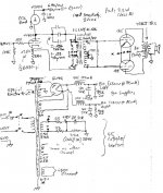
This is a nice skema!!!
Has anyone built this amp, or could provide more information about it?
Thanks
Attachments
There are wrong assumptions and a contradictory conclusion!
The main wrong assumption is that the core responds to applied power. It doesn't! It responds to applied voltage. This the quantity that is related to induction. In fact the very same core can be used for a range of power levels (i.e. voltage into different load). The contradictory conclusion is that he uses a step-up ratio after saying "iron is not good for low signal and low flux density". If one uses the LL1660/10mA as 2:2.25 with 1/2 of the anode current respect to 1:2.25 the DC induction is exactly the same while the signal level will be higher and the capacitive load on the tube will be 4x lower which is always a good thing because tubes don't like capacitive loads....more over in the 1:2.25 connection while the current can only double the primary inductance will be 4x lower respect to 2:2.25. This is a factor that has to be evaluated every time. Some times it works other times doesn't.
I only agree that for low signal level other materials are better but it also depends on the application. So it's not always true.
P.S.
Just to be precise I meant that for the same output level in the 1:2.25 configuration the tube has to deliver lower primary voltage. However because the turns are 1/2 the induction is the same. So the "bad" sound or the higher distortion is likely to come from that specific tube.
The real difference will be at high frequency where the different configuration can have a significant impact. And it depends on the source impedance too, of course.
- Status
- This old topic is closed. If you want to reopen this topic, contact a moderator using the "Report Post" button.
- Home
- Amplifiers
- Tubes / Valves
- push pull 45