Glad to help. I notice that you have tightened the scope of your request somewhat nonetheless
I submit to you for thought that there is an inherent weakness in ALL the PCB's that are available for the Aikido; the dual triodes are split as 1st/2nd stage instead of top/bottom. This is because Vhk becomes a design limitation and the top triodes can't have an elevated heater. My quest for the ultimate Aikido would involve trying P2P construction and using a tube that is both suited for the 1st and 2nd stages, such as a 6DJ8 or a 6SN7 or equivalents.
To go even 1 step further: why use dual triodes? Use 4 tubes/channel. Then you can REALLY optimize.

leadbelly,
I willing to listen to all of the suggestions anybody wishes to make with regard to this aspiration of mine.I'm also happy for all posters to consider the ideas put forth by the other posters to this thread.There would be ideas which a new poster could put forth,which would be instructive to all the other posters.The whole idea of this thread is to consider what may be possible.
I proposing a blank sheet design faithful to the concept of the Aikido.The thing I'm tryin to tease-out of the vast knowledge-base here at diyaudio.com is;
How would we go about getting the absolute best out of this design?
We are getting some fine ideas brought to the board already.Thank you,gentlemen.
Last edited:
By building/listen/voice. Repeat for months.How would we go about getting the absolute best out of this design?
the dual triodes are split as 1st/2nd stage instead of top/bottom
Hmmmm .... not sure if I understand the advantages of this. Would you use two filaments supplies, one referenced to the bottom cathodes and one reference to the top cathodes?
If you did this, it would destroy some symmetry and reduce rejection of noise radiated by the filaments? For example, stage 1 would be exposed to the radiated noise created by two separate filaments supplies, and stage 2 would not create the proper antiphase relationship for cancellation. Instead, the noise could constructively and destructively interact, creating intermodulation and beat harmonics.
using a tube that is both suited for the 1st and 2nd stages
Why create a new requirement of a single tube that is optimized for both positions? The top/bottom configuration disallows dissimilar valve configurations (i.e. 12AT7 for stage 1 and 12BH7 for stage 2). Naturally, you can circumvent this by using 4 valves per channel. You can still use dual triode envelopes, but not connect the second side. Part of the Akikdo circuit is the flexibility of using different valves for the 1st and 2nd stages, so the configuration can be more optimal than the limitations of a single tube for both stages.
p.s. although, I have found the 6CG7 works wonderfully well in both positions.
Yeah now you've convinced me...
Does ultimate only extend to what is audible or also looks")
I have stated repeatedly(elsewhere)that given the choice between a Haut Couture visual designed,poorly sounding component and one which looks like a dog turd with RCAs and a Volume control but which sounded like the hand-picked Angelic Choir:
There is no choice.The dog-turd is the frog-prince whose looks do not reflect what lies beneath.
Gorgeous looking,crap sounding components may as well be left unconnected.They serve their purpose better that way.
If I could have both,why not?The music has to take precedence.Never the other way around.
Single most important thing for performance of the Aikido- the highest B+ you can get away with (careful of heater to cathode ratings!). A well-designed solid state supply with active regulation will pin down the B+ solidly and let the circuit reach its maximum capability. Tube regs are fun and pretty, but vastly inferior in performance.
tube regs are fun and pretty, but vastly inferior in performance.
Tube regs are also inconvenient. They need filament power, burn off a couple watts, and are bigger than diodes.
However, I've found tube regs are highly desirable over solid state when considering sonics. I've tried all sorts of diodes with and without RC snubber networks: Schottky, soft-recovery, FRED, fast, etc.
Tube regs also work much better with constant current than with demand-peak currents. Same thing for choke-filtered power supplies. The impedances of tube regs (DCR impedance) and chokes (AC impedance and DCR) are more favorable for steady-state currents.
This thread broke down into a SS vs. tube reg debate.
Single most important thing for performance of the Aikido- the highest B+ you can get away with.
I run my 6CG7s at about 315V at 10mA, a very nice place on the curves. I could raise the voltage another 25-30V, but it would actually increase output impedance a little. Would require me to swap the power transformer, which isn't that hard, but I'd need to buy new ones.
Well, I can't make a value judgment on the sonic merits of having the supply rail move around with signal and by itself, but if one's view is that the preamp ought not to change the input signal except for a scalar, then an SS reg is unquestionably superior. If one wants the preamp to act as an effects box, then ignore anything I have to say.
My comments on B+ were directed toward linearity. Take a look at the distortion spectrum as you raise and lower the rail voltage. The higher the rail, the lower the distortion AND the greater the reduction in higher order distortion. I posted some results on this a few years ago.
My comments on B+ were directed toward linearity. Take a look at the distortion spectrum as you raise and lower the rail voltage. The higher the rail, the lower the distortion AND the greater the reduction in higher order distortion. I posted some results on this a few years ago.
The higher the rail, the lower the distortion AND the greater the reduction in higher order distortion. I posted some results on this a few years ago.
That was also my experience some time back when tuning a SRPP stage. It's made of a single 6BL7 and runs from a PS at nearly +600V. I use that configuration as the predriver in my 211 SETs. Is there an easy way to find the info you posted?
Maybe you'll find this one useful, too:
http://www.wimdehaan.nl/downloads/nishikiaikido.pdf
Greez
Sigfire
http://www.wimdehaan.nl/downloads/nishikiaikido.pdf
Greez
Sigfire
A well-designed solid state supply with active regulation will pin down the B+ solidly
I built an Aikido headphone amplifier using 6CG7/6H30 and parafeed output transformers. Had it playing for a few months with a CRC supply and then built one of Salas' HV shunt regs to feed it...
The soundstage improved in an amazing way to name the single most important improvement. Highly recommended (...it also sounds better than all my other tube headphone amps using different psu topologies)!
Hello,
It looks like we are speaking of the Aikido here.
My next version is going to use separate triodes at the input. I am going to use 12B4A’s. I have found that for many applications even the 6SN7 or the nine pin version has too much gain. With 1 volt out of a Aikido RIAA amplifier or 2 volts out of a CD player into a 6SN7 Aikido the gain is 10 or 20db.The line stage needs to shunt most of the gain in the attenuator prior to the power amplifier.
Anyone considered an Aikido line stage buffer with switched inputs and an original TubeCad switched attenuator (no input stage, just the cathode follower output stage) with a gain of 1? Less gain to burn.
DT
All just for fun!
If you don't want gain, there are easier (and better) ways of doing a line stage than the Aikido.
Very true, and the same can be said of high gain applications. To steal from Chris Rock: people treat the Aikido like it was Robitussin.
Anyone considered an Aikido line stage buffer with switched inputs and an original TubeCad switched attenuator (no input stage, just the cathode follower output stage) with a gain of 1?
Without both stages, the circuit loses the symmetry, and therefore, loses the noise cancellation feature.
I have found that for many applications even the 6SN7 or the nine pin version has too much gain.
Boy, do I agree to this! The Aikido needs to be matched with very low gain power amplifiers. My Pass Zens, Pass F4, and my EL84 push-pull all have very low input sensitivities for this reason. There's too much gain everywhere! I'm a huge activist against Gain Poising.
The higher the rail, the lower the distortion AND the greater the reduction in higher order distortion. I posted some results on this a few years ago.
Yea, I've already decided to purchase another set of transformers (two required for dual mono) to try higher voltage. I'll have to change some cathode resistors to adjust bias currents, and maybe the filament reference.
Well, I can't make a value judgment on the sonic merits of having the supply rail move around with signal ...
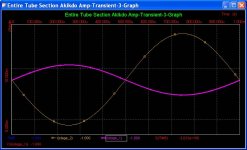
The Aikido stages operate in antiphase, allowing much of the signal current to cancel (depends on tube selection). See image of current simulation for stage 1 (purple) and stage 2 (yellow) at 1kHz using 6CG7s into a 5k load. After cancellation, the power supply sees only 3mA of ripple current (according to simulation). My Aikido operates into a 40k load, therefore, my currents are correspondingly lower by a factor of 8.
Looking at the impedance of the power supply, the output capacitor easily passes the current ripple. However, the choke acts as very high impedance and stops it cold. The output capacitor of the power supply is important, as with any power supply design, as it is the first line of defense against signal-induced current ripple.
Well, I can't make a value judgment on the sonic merits of having the supply rail move around ... by itself.
With the CLCLC configuration I'm using, the time constant for the power supply to move around "by itself" is very long (several orders of magnitude) relative to the signal of interest (audio band). That being said, I've never measured my B+ voltage on any given day different than another day. By (non-six-sigma) observed circumstantial evidence, I have never seen B+ "moving around ... by itself". I presume this would be caused by perturbations in the utility service. I'll wire up an LCD panel-mount voltmeter over the next couple months and keep an eye on things.
SS reg is unquestionably superior.
Superior, as in having "low AC impedance". However, what do you have downstream of the rectifier? If you have a choke, any impedance benefits that your SS reg offers is lost at the choke.
Counter to the impedance benefit, SS liabilities include poorer power factor (narrow conduction times), higher peak currents, and commutation noise. SS rectification requires larger filter capacitors to handle the peak currents and hold the charge a longer duration until the next peak. In comparison, valve rectification has longer conduction times, lower peak currents, and less demands on the filter capacitors - and no commutation noise or snubber networks!
Attachments
Last edited:
Such as? (You knew this was coming, didn't you?)
Modesty prevents me... oh, no, it doesn't.
SYclotron Audio » The Heretical Preamp
Superior, as in having "low AC impedance". However, what do you have downstream of the rectifier? If you have a choke, any impedance benefits that your SS reg offers is lost at the choke.
I don't believe that's the case. If the reg has voltage headroom, its AC impedance (and for that matter, the DC impedance) is not dependent on the stuff before it.
- Home
- Amplifiers
- Tubes / Valves
- Looking for the Ultimate Aikido.