Hi guys,
Need your brains here. It's very many years since I did anything with vinyl but I still have some and thinking of getting those old black discs out!
I built the Moving Coil Passive RIAA Phonograph Pre-Amp, Fig 4 in the LT1115 applications sheet. I used a LT1028 in the first stage - this design is virtually the same as the Michel ISO. Sounds nice and did me fine, but not the ultimate!
See page 12 on:
Linear Technology - LT1115 - Ultra-Low Noise, Low Distortion, Audio Op Amp
My question is whether I can use the first stage of this, including the passive eq up to the input of the second op amp, and run it into a tube second stage.
Then the question is what sort of gain I'd need from this following tube stage for a MC cartridge. And of course any suggestions for what sort of tubes. I have many DHT types (gain up to 15) including the useful 3a5, plus I have 5842, 8532, 6GK5 and many more.
How do I complete this schematic? I'm pretty basic with solid state, though I've built a lot with tubes.
andy
How do I complete this schematic? I'm pretty basic with solid state, though I've built a lot with tubes.
You get rid of it. That circuit looks like 100% active EQ in a GNFB loop. No sir! Jim Hagerman's "Bugle" will sound better, in an all opamp phono pre.
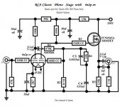
You want to use a LOMC, right? Allen Wright's hybrid cascode using low noise JFETs "downstairs" and 6GK5s "upstairs" will provide the large amount of gain needed before a passive EQ setup. Use whatever tickles your fancy after the EQ network, but I'd stay away from DH tubes for S/N reasons. The buffered 2nd gain block in the tweaked RCA circuit I've uploaded should serve you well. AAMOF, lack of cash is stopping me from executing the very setup I've mentioned.

Attachments
Eli -
I think you are looking at the active feedback schematic on the LT1115 applications sheet - the first you come to. The one I'm referring to is on page 12 and it's passive. Take a look and let me know!
Also, in this RCA classic schematic with the 6n2p, where's the cathode bias for the second tube stage? The original is 2.7k
best
andy
Andy,
Why are youposting SS questions in the Tubes forum?
Eli is right, you can do a far better job with tubes. But I'd suggest building my whole FVP5A phono stage, and NOT using a MOSFET to buffer it. That is throwing the baby out with the bathwater!
Circuit is on my website under the "Schematics" button, with more info & schematic under "Secrets of the Phonostage" linked here:
http://www.vacuumstate.com/fileupload/SP_15_Article.pdf
It sounds great!
Regards, Allen
Eli -
I think you are looking at the active feedback schematic on the LT1115 applications sheet - the first you come to. The one I'm referring to is on page 12 and it's passive. Take a look and let me know!
Also, in this RCA classic schematic with the 6n2p, where's the cathode bias for the second tube stage? The original is 2.7k
best
andy
I took a 2nd look. The design on the linked page is active EQ. However, the schematic on page 12 of the data sheet is passive EQ.
Look at the tweaked RCA schematic again. The 2nd gain block is grid leak biased. Grid leak biasing the 2nd gain block improves bass extension, by easing the load on the EQ network. Thank you, Thorsten Lösch. If you are going to try that design, some parts value changes are in order. The interstage coupling cap. needs to be 180 nF. and the 470 KOhm part should drop to approx. 255 KOhms. FWIW, I recommend the clean and quiet Sovtek 12AX7LPS as the tube.
Eli - I don't understand the biasing on the second stage of the Classic RCA schematic - as far as I can see the grid is at zero volts DC together with the cathode. What am I not understanding here!
Allen - your circuit looks like a very good idea indeed!
andy
Andy,
There are 2 ways to self bias a tube: the ubiquitous cathode technique and grid leak, AKA contact.
Some thermionic electrons strike the grid. When the grid to ground resistor is very large (here 20 MOhms) those electrons are slow to bleed off and an equilibrium is established. The grid biases up to roughly 2 V. Grid leak bias works only in low signal level conditions, which is exactly the situation in a phono preamp. The most common use of the technique is in AM radios. Google "grid leak detector".
BTW, the grid to ground resistor limit found in tube data sheets deals with unwanted contact bias effects that destabilize the device.
Andy,
Construct a well filtered and well regulated 250 V. B+ rail and everything else will fall into place. IIRC, IB is somewhat less than 1 mA. in both triodes.
For the sake of completeness, RCA's original schematic has been uploaded.
Construct a well filtered and well regulated 250 V. B+ rail and everything else will fall into place. IIRC, IB is somewhat less than 1 mA. in both triodes.
For the sake of completeness, RCA's original schematic has been uploaded.
Attachments
- Status
- This old topic is closed. If you want to reopen this topic, contact a moderator using the "Report Post" button.
- Home
- Amplifiers
- Tubes / Valves
- Phono stage with LT1028 MC input