and if so, does it appear complete?
7025 is the tube incorporated with pic 1, the circuit in question.
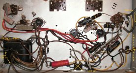
i dug up an old radio, like 14 tube or so, tore the amp out and what appears to be a pre to me.
what i assume the wiring is;
south b+, north input, west 12vdc, east output
i figure i will check here before i let the sparks fly.
7025 is the tube incorporated with pic 1, the circuit in question.
i dug up an old radio, like 14 tube or so, tore the amp out and what appears to be a pre to me.
what i assume the wiring is;
south b+, north input, west 12vdc, east output
i figure i will check here before i let the sparks fly.
Attachments
Last edited:
i am a bit confusing sorry,
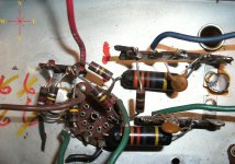
in question is this small circuit, i am wondering if it appears to be complete, i carefully removed it from the radio portion of the unit, it appears to be a pre of sorts,
b+(red south)
12v (brown black)
output (blue green)
input (north)
if i wire this this way, prehaps it will work? i will do so with extreme caution, just looking for a second opinion..
Attachments

It is a pre but your red (which IS B+) heads north in the pic which is even more confusing.
The black, on the terminal strip with the blue output, will need to be grounded to the terminal next to the red B+ or that channel won't work.
The brown-left and the black bottom are the heater connections.
I also don't understand the outputs being taken through small disk ceramic capacitors. I would take the outputs directly from the plates (trace the outputs back to the tube to find the plates, blue traces back to pin 1 of the 7025, green o/p to pin 6) via a 0.1uF 400v film cap. There's not much bass going to go out via the existing caps, unless the following stage is VERY high impedance.
I suggest downloading the 7025 datasheet to become familiar with this circuit and the pins of the tube, before using it for anything outside the original box. You will see how it is similar to the section in the main amp box, but with some crucial differences as well.
Gary
You didn't say whether you still had the tubes for the amp chassis, but that has the potential to be a nice little SE stereo amp of about 5wpc. I just built one like it with a 6N3 instead of the 7025 and it sounds far better than it should given the tiny 50 year old transformers that are similar to yours.
It is a pre but your red (which IS B+) heads north in the pic which is even more confusing.
The black, on the terminal strip with the blue output, will need to be grounded to the terminal next to the red B+ or that channel won't work.
The brown-left and the black bottom are the heater connections.
I also don't understand the outputs being taken through small disk ceramic capacitors. I would take the outputs directly from the plates (trace the outputs back to the tube to find the plates, blue traces back to pin 1 of the 7025, green o/p to pin 6) via a 0.1uF 400v film cap. There's not much bass going to go out via the existing caps, unless the following stage is VERY high impedance.
Gary
the stereo amp is awaiting a 6ca4 tube, i currently have none, the amp looks simple and clean, a bit better than the other in my prior posts, its just one of many projects i want to rap up before spring, i just found a cool widow-maker ac/dc amp, just two 50c5 and one 12ax7..
ok very cool advice on the pre circuit! it is what i was hoping one of the many tubesperts here would provide. i was comparing with other 12x7 one tube designs and taking in what you stated and it makes a bit more sence now, having the pre designed along side with amp is perfect for my tubed boombox project. i only need now to figure out how and if i can get it all sounding sweet. then wire it to a cassette head and squeeze it into a boombox, non-cordless of course, i am tring to locate a tube 8 tract for the pick up..
any ways sorry about the confusion north south, left right i am a bit dislexic, perhaps i ate to many resistors when i was a child, hey they looked tasty, and i manage.
I'm no tubespert, far from it, I'm quite new at this too, just noticed it looked similar to some stuff I had just been playing with and thought I could help a little.
Now, whether it has the gain (and the right equalization) needed to run from a tape head directly is another thing entirely. I was assuming you wanted a flat-response line stage. However, if you can find a tube stage that does the tape-head equalizing, that just needs a little gain, then the 7025 one will certainly work.
Now, whether it has the gain (and the right equalization) needed to run from a tape head directly is another thing entirely. I was assuming you wanted a flat-response line stage. However, if you can find a tube stage that does the tape-head equalizing, that just needs a little gain, then the 7025 one will certainly work.
today i found the 6ca4 i needed for this project, the power amp uses two 6bq5, 7025, 6ca4....
can i use a standard ge 12ax7 on this amp, in place of the 7025?
edit; i found the answer and it is yes, my bad
i know there interchangeable though i want to check here first.
ooo i get to go fire it up and see what it dose, nothing like turning that varaic up and seeing what an old amp/radio is going do, smoke, humm, perrr, explode, or just sound sweet. a few years back i resold old radios, and knowing little of how to fix them besides swamping components, i blew allot up, ignorance maybe but i was making money and had little time and space. i will never forget watching a heath kit w7 catch fire, while extinguishing it i smashed two pricey 6550's, and two mullard 12ax7's, bent the chassis and mutated a toe. well off to play in the shop.
thanks
jordan
Last edited:
Was the 6CA4 new or the original? Are there sparks inside the 6CA4 when this happens?
Does it buzz without the 6CA4 plugged in? If so, the power transformer may be history Or there is a short on the heater lines (unlikely unless you altered something)
Assuming it's still buzzing with all tubes unplugged, check the voltages coming out of the transformer. Careful, the ac on the HT winding could be well up over 300v. I suggest disconnecting any heater wiring you added/altered first to see if that helps.
If it stopped buzzing without the 6CA4 (rectifier), then the problem is along the high voltage DC (hvdc) line. Again this is where a schematic makes it easier for those of us who can't be present to see what is going on.
This is also where it could get risky. I could suggest disconnecting the hvdc that leads from the 6CA4 to the rest of the tubes and checking the hvdc, but doing that will drive the DC voltage quite high and the risk of exploding the big old filter capacitor (top left of pic, the can shaped thing that sticks thru the chassis) becomes greater if it's not in good condition. It could be what is causing the buzzing if it begins to get warm after a short time. If so, it's probably toast and will go bang at some inconvenient time and must be replaced.
Hope that helps, and BE SAFE while doing these measurements. Read the sticky thread on this forum about safety, as your life depends on it.
Does it buzz without the 6CA4 plugged in? If so, the power transformer may be history
Or there is a short on the heater lines (unlikely unless you altered something)Assuming it's still buzzing with all tubes unplugged, check the voltages coming out of the transformer. Careful, the ac on the HT winding could be well up over 300v. I suggest disconnecting any heater wiring you added/altered first to see if that helps.
If it stopped buzzing without the 6CA4 (rectifier), then the problem is along the high voltage DC (hvdc) line. Again this is where a schematic makes it easier for those of us who can't be present to see what is going on.
This is also where it could get risky. I could suggest disconnecting the hvdc that leads from the 6CA4 to the rest of the tubes and checking the hvdc, but doing that will drive the DC voltage quite high and the risk of exploding the big old filter capacitor (top left of pic, the can shaped thing that sticks thru the chassis) becomes greater if it's not in good condition. It could be what is causing the buzzing if it begins to get warm after a short time. If so, it's probably toast and will go bang at some inconvenient time and must be replaced.
Hope that helps, and BE SAFE while doing these measurements. Read the sticky thread on this forum about safety, as your life depends on it.
why thank you for the advice, i take safety first, i use a shield over the caps when testing and all other necessary measures.
the amp was buzzing with out tubes,,,i discovered the chassis was running 12vdc hot, a lead for the radio's luminescent was bent touching the chassis... eaggg should have looked better before i turned on, the short was on the top tubed side witch i overlooked.
after 3 more long stare downs the amp was fired up and works great, there is a real scratchy short coming from the 7025 tube socket, a very faint quiet crackle-fizz, besides that clean loud and i didn't listen to long, i will get the schematic and some post surgery pics up.
- Status
- This old topic is closed. If you want to reopen this topic, contact a moderator using the "Report Post" button.
- Home
- Amplifiers
- Tubes / Valves
- ID request, is this a pre?