Time for a rethink maybe.....
I think so. Even with low RP 6922s, the unbuffered Bottlehead Seduction is supposed to be used with 50 KOhm or greater loads.
IMO, buffering the O/P is the way to go. I believe in allowing for a worst case scenario. Worst case being the FUGLY 10 KOhm IHF "standard" load. The little ZVN0545A MOSFET handles things with aplomb and it's very easy to set up.
Arne, you read my mind.
Those 1% caps in the RIAA are difficult to find Arne. Where did you get yours?
Check this out Eli. I've added the mosfet to the 5670 circuit. No idea if I've done it right.

I don't for one minute think the mosfet will make the sow's ear into a silk purse but it's easy to do so I'd be daft not to try that first.
Those 1% caps in the RIAA are difficult to find Arne. Where did you get yours?
Check this out Eli. I've added the mosfet to the 5670 circuit. No idea if I've done it right.
I don't for one minute think the mosfet will make the sow's ear into a silk purse but it's easy to do so I'd be daft not to try that first.
As drawn, the buffer will not work, regardless of the FET chosen. Neither an enhancement type nor a depletion type has its gate properly biased.
To make things work with the ZVN0545A or other enhancement MOSFET, connect the FET's gate stopper directly to the tube's plate and move the RIAA network connection to the circuit's O/P point. The ZVN0545A is ideal for this job, as its capacitances are tiny. Even the wimpy 12AX7 has no trouble driving a ZVN0545A.
The O/P coupling cap. is sized according to the downstream load impedance. It needs to be no smaller than 3.3 μF., if 10 KOhms is to be driven. Part of the poor performance of the unmodified 5670 circuit can be traced to the 0.1 μF. coupling cap. at its O/P. For that value to work well, the downstream load has to be (sic) >= 300 KOhms. Lower valued loads induce loss of bass.
To make things work with the ZVN0545A or other enhancement MOSFET, connect the FET's gate stopper directly to the tube's plate and move the RIAA network connection to the circuit's O/P point. The ZVN0545A is ideal for this job, as its capacitances are tiny. Even the wimpy 12AX7 has no trouble driving a ZVN0545A.
The O/P coupling cap. is sized according to the downstream load impedance. It needs to be no smaller than 3.3 μF., if 10 KOhms is to be driven. Part of the poor performance of the unmodified 5670 circuit can be traced to the 0.1 μF. coupling cap. at its O/P. For that value to work well, the downstream load has to be (sic) >= 300 KOhms.
Lower valued loads induce loss of bass.The O/P coupling cap. is sized according to the downstream load impedance. It needs to be no smaller than 3.3 μF., if 10 KOhms is to be driven. Part of the poor performance of the unmodified 5670 circuit can be traced to the 0.1 μF. coupling cap. at its O/P. For that value to work well, the downstream load has to be (sic) >= 300 KOhms.
And that's exactly what I have with this phono stage. A thin sound and no bass. Part of the problem may be down to my amps and pre amp. I run three AVC integrated tube amps with the source switching and volume pots removed and fed by a McCormack TLC 1 Line Drive in passive mode. For all intents and purposes I've just put the switching and volume pots on the outside of the amps though I appreciate the input impedance of the TLC1 will be lower than that of the integrated amps.
Maybe I should build another passive with a 100K pot and the necessary source switching but with a seperate buffer for each output.
A 100 KOhm buffered volume control is too "short". Just add the buffers, with 3.3 μF. O/P couplers, to the phono preamp. Film and foil (330 nF.) bypassed Solen, GE, or Wima MPPs will be fine.
If sourcing the ZVN0545As becomes problematic, drop Jim McShane a line. Jim is 100% reliable and he ships world wide.
Once again, hate to throw off your plans as you've though about this a bit, but if it was ME, I would leave the board completely alone, put the MOSFET at the output of the board (AC coupled by the original caps, which are adequately sized for the MOSFET input impedance), and add the 3.3uF caps after that.
Once again, hate to throw off your plans as you've though about this a bit, but if it was ME, I would leave the board completely alone, put the MOSFET at the output of the board (AC coupled by the original caps, which are adequately sized for the MOSFET input impedance), and add the 3.3uF caps after that.
The thrust of that thinking can be implemented, as the NFB take off point is isolated between 2 capacitors. However, some rearrangement will be necessary. The existing safety discharge resistor can become the FET's Gate resistor, but it can't go to ground. Enhancement mode FETs require forward bias and depletion mode FETs require reverse bias. A high transconductance (gfs) "N" channel JFET is fine, given cap. coupling. Assume the FET's internal resistance is zero Ω, even though it's not. Pick a Source load resistance value that yields an ID of 3.5 mA., in combination with the B+ rail voltage. Tap down that resistance to get approx. 1.5 V. of reverse bias. The gate resistor connects to the tap. Notice that this setup is exactly like an I/P cap. coupled cathode follower. Install 1/4 W. parts directly across the O/P jacks' solder lugs, to serve as the new safety discharge resistors.
The thrust of that thinking can be implemented, as the NFB take off point is isolated between 2 capacitors. However, some rearrangement will be necessary. The existing safety discharge resistor can become the FET's Gate resistor, but it can't go to ground. Enhancement mode FETs require forward bias and depletion mode FETs require reverse bias. A high transconductance (gfs) "N" channel JFET is fine, given cap. coupling. Assume the FET's internal resistance is zero Ω, even though it's not. Pick a Source load resistance value that yields an ID of 3.5 mA., in combination with the B+ rail voltage. Tap down that resistance to get approx. 1.5 V. of reverse bias. The gate resistor connects to the tap. Notice that this setup is exactly like an I/P cap. coupled cathode follower. Install 1/4 W. parts directly across the O/P jacks' solder lugs, to serve as the new safety discharge resistors.
That's given me brain overload and as I've not long been home from my toils and I'm very tired I'll think about it in the morning.
Good night all.
Si.
Please check this out Eli to see if I've done it right,
However, I've realised that I've no desire to mess around with the 5670 phono stage. I'm not happy with the active RIAA either, so after a lot of thought I'm favouring Eli's mosfet buffered RCA circuit. There's a few reasons for my decision, not least that it's already worked out. I don't have to mod another circuit and Eli reckons it works and sounds fine. I can use my existing psu too. I have a similar psu on a full function pre amp and it's dead silent.
So finally, in the RCA circuit I see reference to oil caps and other esoteric stuff. Are these really necessary?
An externally hosted image should be here but it was not working when we last tested it.
However, I've realised that I've no desire to mess around with the 5670 phono stage. I'm not happy with the active RIAA either, so after a lot of thought I'm favouring Eli's mosfet buffered RCA circuit. There's a few reasons for my decision, not least that it's already worked out. I don't have to mod another circuit and Eli reckons it works and sounds fine. I can use my existing psu too. I have a similar psu on a full function pre amp and it's dead silent.
So finally, in the RCA circuit I see reference to oil caps and other esoteric stuff. Are these really necessary?
Please check this out Eli to see if I've done it right,
However, I've realised that I've no desire to mess around with the 5670 phono stage. I'm not happy with the active RIAA either, so after a lot of thought I'm favouring Eli's mosfet buffered RCA circuit. There's a few reasons for my decision, not least that it's already worked out. I don't have to mod another circuit and Eli reckons it works and sounds fine. I can use my existing psu too. I have a similar psu on a full function pre amp and it's dead silent.
So finally, in the RCA circuit I see reference to oil caps and other esoteric stuff. Are these really necessary?
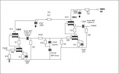
The schematic is still wrong. There isn't any bias on the FET's gate. Once the gate is AC coupled, use a JFET. JFETs set up like tubes, except for voltages.
The tweaked RCA schematic was drawn, from a narrative I provided, by Buzz. Buzz loves boutique parts, but they are not really necessary. Tightly match a pair of high quality 220 nF. parts for the interstage couplers. Soviet surplus paper in oil (PIO) are good, as are MultiCap RTX and PPSFX. The 470 KOhm resistance should drop to 255 KOhms. I suggest a 3.3 μF. metalized polypropylene cap. bypassed by a 330 nF. polypropylene film and Aluminum foil part, as the O/P coupler. A Solen and a 716P series Orange Drop are fine.
BTW, mixing dielectric material types up is a good idea. That way, you hear the circuit, not the capacitors.
Eli's phono
I can vouch for this one. Eli hit the nail on the head with his tweaks. At one point I built up the original RCA phono stage, but was never happy with it. The output impedance was just too high. The ZVN0545A source follower sure solved that problem. I also mixed up the caps, coupling with a russian teflon bypassed with a vitamin Q, and the output is a metalized polypro. I've only been using it with MM carts so far. It's the third phono stage I've built and I don't see the need to try another.
Dan
The schematic is still wrong. There isn't any bias on the FET's gate. Once the gate is AC coupled, use a JFET. JFETs set up like tubes, except for voltages.
Sorry Eli, you've totally lost me there. No matter as I won't be going down that route.
Anyway I know which way I'm going now and thanks for the thumbs up Dan. However I'll be working long hours for the next twenty one days, so progress will be somewhat slow.
Quanghao, thanks for the circuit diagram. I'll certainly file it for future reference but it doesn't fit in with the current scheme of things.
Si.
Hi all.
I'm still in the process of getting the parts together to build the RCA phono stage.
Eli, I'm having problems finding 30uf caps without breaking the budget. I've located some decent motor run caps but they're a bit big at something like 75mm X 45mm. If you thought they'd do the job I'd squeeze them in.
This is where I'm up to;
Original phono board removed and some mild steel angle fitted to carry the valve bases. Heaters wired in series:

I'm still waiting for some of the components but here's what I've got so far:

Ok, the project's a bit slow due to my work schedule but I'm getting there
Bet you thought I'd given up
Original phono board removed and some mild steel angle fitted to carry the valve bases. Heaters wired in series:
I'm still waiting for some of the components but here's what I've got so far:
Ok, the project's a bit slow due to my work schedule but I'm getting there
Bet you thought I'd given up
- Status
- This old topic is closed. If you want to reopen this topic, contact a moderator using the "Report Post" button.
- Home
- Amplifiers
- Tubes / Valves
- 5670