Folks,
I've been building this 6LU8-based Spud for a while now. I had the prototype working in a point-to-point rats nest. I considered moving the rats nest into a chassis, but opted to design a PCB for it instead. I followed attached schematics for the layout and am confident everything is connected according to the schematic.
I have one issue with it: In the original rats nets, I was getting about 4.7 W output into 8 ohm at 1.7 % THD (if memory serves). After the circuit was moved to a PCB, I'm getting a little over 2 W at 3 % THD. The amp clips HARD if I try to go much beyond that. It's the output stage that's clipping.
I made a couple of changes from the original circuit: R1, R2 have been replaced with a 2 W type (were 5 W). R3 has been changed from a 1 kOhm, 1/4 W metal film to a 1 kOhm, 2 W, metal oxide film. And C3 has been changed from 1200 uF to 100 uF. C4 was added.
I have tried connecting the 1200 uF in parallel with the 100 uF and that doesn't change anything. Neither does removing C4.
This is truly bizarre. It's almost as if the output stage is running in triode rather than UL.
Currently I'm using a pair of lab supplies to deliver heater voltage and B+. Same lab supplies as I used for the rats nest...
Could one of you shed some light on what might be going on here?
Thanks,
~Tom
Attachments
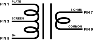
For the OPT connector:
B+ --> Pin 1 of OPT
SCREEN --> Pin 3 of OPT
PLATE --> Pin 5 of OPT
OUTP --> Pin 7 of OPT (Speaker +)
OUTN --> Pin 9 of OPT (Speaker -)
I'm using the Edcor XSE15-8-5K.
The cathode current measures 58 mA (32 V across 560 ohm).
Thanks,
Tom
B+ --> Pin 1 of OPT
SCREEN --> Pin 3 of OPT
PLATE --> Pin 5 of OPT
OUTP --> Pin 7 of OPT (Speaker +)
OUTN --> Pin 9 of OPT (Speaker -)
I'm using the Edcor XSE15-8-5K.
The cathode current measures 58 mA (32 V across 560 ohm).
Thanks,
Tom
Attachments
B+ --> Pin 1 of OPT
SCREEN --> Pin 3 of OPT
PLATE --> Pin 5 of OPT
OUTP --> Pin 7 of OPT (Speaker +)
OUTN --> Pin 9 of OPT (Speaker -)
Your hook up doesn't match the Edcor picture that you enclosed. The PLATE and B+ wires are swapped. If I remember right the XSE15-8-5K inverts the phase, so you might need to intentionally swap the secondary leads also. Try it both ways.
I built a similar amp using a 6LR8 and the XSE15-8-5K. If I remember right I was getting about 5 watts out of it.
George,
You're right. I now wonder if I wrote down the pin numbers incorrectly when I typed the post above or if I connected the transformer incorrectly. It would certainly make sense that I got lower performance if I was using a 60 % tap rather than a 40 % UL tap.
I'll have to double - no tripple - check the connections when I get home.
I'll report back my findings. I used to get 4.7 W before SOFT clipping on the top of the sine wave. Now I get 2~2.5 W and HARD clipping on the bottom of the sine wave. Maybe I was too tired last night when I hooked up that tranny...
Thanks,
~Tom
Check the feedback connection as well when you hook up the primary the other way around. Some positive feedback could drive the tube into clipping but not result in audible oscillation if feedback ratio was low enough.
If I was in your situation I'd try to get straight pentode mode sorted out first and then just move the screen connection to the UL tap.
If I was in your situation I'd try to get straight pentode mode sorted out first and then just move the screen connection to the UL tap.
I do recall having to swap the connection on the secondary to get rid of oscillations. After this change, it looks like the amp had about the expected gain so I thought everything was fine and dandy until I started measuring distortion.
When I wrote up my post this morning, I noticed that the connection to the secondary looked "wrong", but I didn't have time to dive into it in more detail. I was comparing the colors of the wires on the transformer I had connected to the circuit vs the transformer that I still have sitting disconnected (but with bits of wires still attached to its terminals). I wonder if I accidentally swapped the B+ and the PLATE connections...
I'll know more in a few hours when I get myself home from work...
~Tom
So I went back to the original circuit. I inserted replacement components in places where I had harvested components. I get the same result as I get on the PCB. This just blows my mind.
The DC resistance of the OPT between PLATE and SCREEN/UL is 50 ohm. Between the UL tap and B+ is 38 ohm. So I should have the taps connected right.
Distortion increases linearly (give or take) with power. I get roughly 1.5 % at 1 W, 3 % at 2 W followed by a rather dramatic increase after that. In the original circuit, I had < 1 % up to 2 W, 2.4 % at 4 W, and 3 % at 4.5 W.
I tried connecting the tube as a triode by connecting the SCREEN to PLATE on the transformer. That lowers the gain by about 2x but aside from this, nothing seems to change. The max power before clipping is about 3-4 W and the distortion is about the same as for UL operation. I have measured with an ohmmeter that the resistance from the UL tap on the transformer to the screen pin on the tube (measured by lifting the tube slightly out of the socket and measuring directly at the pin of the tube) is the 1 kOhm it should be.
I have tried replacing the tube with a different sample that I hadn't used before. I also tried replacing the OPT. Same result...
This is truly bizarre!
~Tom
Last edited:
THANKS GEORGE!!!!!!!
I re-read your post and noted the following statement, "If I remember right the XSE15-8-5K inverts the phase [...]".
You are absolutely right. It does invert the phase. That's why the secondary connection looked "wrong" when I looked at it this morning.
I swapped the OUTP and OUTN connections and I'm now back to normal. < 1 % THD at 1 W and max power on the order of 5 W at 3 % THD. Time for a cup of tea followed by bedtime...
Thanks to everybody who contributed.
Thanks,
~Tom
I re-read your post and noted the following statement, "If I remember right the XSE15-8-5K inverts the phase
It stands to reason that if negative feedback can reduce distortion and increase the power output, positive feedback can have the opposite effect. I have confirmed this on a Simple SE by accident. I was using the little Edcor OPT too. There are a few SE OPT's that invert the phase. The little Edcor is one, I think the big Edcor does too, and there are a few others. If I was a bit more organized I would start a list.
I'm fairly confident the big Edcor (CXSE25-8-5K) inverts the phase as well. I had one of those rigged to my spud for a while and used the same connections as for the little Edcor.
What's interesting is that the positive feedback didn't seem to cause instability. At least I didn't notice anything out of the ordinary on a 400 MHz o'scope and 0-100 kHz spectrum. But I guess in the end the negative feedback from the UL tap to the screen grid was dominating over the positive feedback from the secondary to the cathode and kept the amp stable. Either that, or I couldn't pick up the signs of instability with my gear. A spectrum analyzer that extends beyond my current 100 kHz capability would be nice.
One thing, though. When the amp is running normally - well below clipping, it has mostly 2nd and 3rd order harmonic distortion. There's a little bit of 5th peeking up from the noise floor. With positive feedback, I get an entire forest of harmonics. Just an interesting tidbit of information.
Anyway. Thanks!!
~Tom
Last edited:
- Status
- This old topic is closed. If you want to reopen this topic, contact a moderator using the "Report Post" button.
- Home
- Amplifiers
- Tubes / Valves
- Spud issues - a little help, please