There is a local friendly competition to build an amp using the 6V6 as the output stage. This is the only requirement, so please do not suggest some other tube, for the output stage.
I know there are a number of existing designs I could use, but I'm trying to come up with my own design as a way of learning. I've read a number of tutorials including the one at Boozhound Labs, but I haven't been able to find a good explanation of the driver stage.
No so much "what is it" but more along the lines of what factors determine what circuit to use, what tube to use, etc?
The Boozhound example uses a simple 6SN7 grounded-cathode for the driver stage. Why is this a good tube (other than its supposed to sound good)? I'm guessing it has to do with the gain, but I'm not sure. If it does have to do with gain, how do I determine how much gain I need?
I'm guessing there isn't a simple answer to these questions, but if you can point me in the right direction, I will be grateful.
+1 on the Morgan Jones!
As I see it ...
Step 1: how much voltage?
If you're doing a single-ended triode-connected output stage as per the Boozhound example, the driver needs to provide +-12.5 volts at it's output (about 9 volts rms).
Hmm ... Perfect job for an op-amp! Maybe a nice vintage 741 to go with with whole "retro" vibe? (OK, I'm kidding, please don't do that)
Step 2: how much gain?
For a zero feedback design (like the Boozhound), a voltage gain of at least about 10 is enough. In their example, the input stage has a voltage gain of 15, so the amp will require an input of 600mV rms for full output. (600mV * 15 = 9V) Perfect!
If you wanted to use overall negative feedback, then you'd need higher gain - maybe 50 or so, allowing for reduction by a factor of 4 or 5 when feedback is applied.
Step 3: what topology?
That's easy - if you want voltage gain, you need to use a grounded cathode arrangement. Exception: if you want to use a balanced input, then a long-tailed-pair input stage is needed.
So far, so easy - almost any tube can give 9V rms out and have enough gain.
Now for the hard part:
Step 4: choosing the tube, operating point etc
There's at least 3 options here:
Plan A: Aim for least possible distortion from the input stage.
Plan B: Try to get the right amount of distortion from the input stage to cancel out the distortion from the output stage as best as possible.
Plan C: Worry less about distortion and find something that sounds good.
Plan B sounds smart but there's a slight complication - output stage distortion depends on the load, and even the same speaker will load the output stage differently at different frequencies, so it's a bit like trying to hit a moving target.
Other random thoughts:
For the input stage, you might want to consider noise and microphony, although that's more an issue with low-level signals (e.g. in phono pre-amps.). Shouldn't be a problem here.
Too much voltage gain is no problem - you can always use cathode degeneration to reduce gain (and reduce distortion at the same time).
I'm guessing there isn't a simple answer to these questions, but if you can point me in the right direction, I will be grateful.
There isn't a simple answer here. Although 6V6s aren't exactly a hard load, so that does simplify things a bit.
First of all, you didn't mention how you intended to use those 6V6 finals. Are you going to make pseudotriodes, or use 'em pentodes? This makes a big difference. As a pentode, the reverse transfer capacitance, and hence the Cmiller, will be less. This consideration is an important one since the combined Cmiller + Cgk + Cstray needs to be charged up fast enough to avoid slew limiting at the high end.
6V6 Specs:
Crt= 0.7pF
Cgk= 9.0pF
Rl= 10K (P-2-P)
Po= 10W
Vi=30V(p-p)
Given that, the output at the plate will be: 158.1Vrms or 223.6Vp. The gain is therefore: 15.
Cmiller= 0.7(1 + 15)= 11.2pF
Ci= 11.2 + 9.0 + 10= 30.2pF (Guesstimate Cstray= 10pF)
This gives: Bc= 2pi(30E3)(30.2E-12)= 5.7E-6 (A/V) At 30KHz.
The current that will demand: I= 15 X 5.7E-6= 0.1mA
Your driver should have a minimum current of: Ipq= 5 X 0.1= 0.5mA (By the "Rule of Five" borrowed from solid state practice).
The 6V6 really isn't a formidable load by any means. Of course, this doesn't include the possibility of grid current, which will surely flow during over drive. Still, coming up with a driver isn't that big of a problem. A 6SN7, or one of its relatives, will do nicely here.
Then there is the question of whether this design is going to be single ended or push-pull? Use gNFB or not? That, too, makes a big difference.
Last edited:
On second thoughts, if you want more than half a flea-power peak output from the 6V6, you'll have to drive it into grid-conduction.
Driving it with a DC-coupled cathode-follower could do the trick.
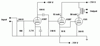
Something like shown below should be able to kick the **** out of the 6V6 quite comprehensively and give you an extra 5 or 6 dB headroom.
 (especially with fixed bias)
An input stage with more voltage gain might help too.
Driving it with a DC-coupled cathode-follower could do the trick.
Something like shown below should be able to kick the **** out of the 6V6 quite comprehensively and give you an extra 5 or 6 dB headroom.
(especially with fixed bias)An input stage with more voltage gain might help too.
Attachments
hey-Hey!!!,
I've been looking at that same contest/requirement myself...") The thought process went something like this:
The thought process went something like this:
How much output voltage do I need? Seems that +/- 20V should cover it nicely. Getting that much from a 250V( give or take a little ) is easy with nearly every single possible choice of tube so on to the next...
How much gain? Given likely linestage availability, I figured 10 would be a reasonable minimum, with something like 50 ( in terms of volts/volts ) would be acceptable. Still within capability of *MANY* good options.
What sort of loading will the power stage present? I'm looking at U-L( or partial triode ) rigging, so it will be between half and a quarter of the triode-rigged input capacitance. Not so large a load that a 10kOhm output impedance from the driver would be working hard. To go one step further, it would want to be idling at between 3 and 10 mA so as to be unpreturbed by the current demands of the load. Still no issues with any likely choices.
So...what will the topology be? Simplicity given the parts bill is a large concern. I settled on the E-Linear circuit. Likely running an EF184 pentode. This simplifies the B+; only a single well-filtered delivery to the amp is made to the OPT. The EF184's plate load is supplied through the U-L tap on the output. Type 12HL7 is another option( and at $2/tube for a known good performer it will certainly get tried ).
Then there is the power supply. B+ around 250V at around 100 mA for a stereo SE amp is fairly easy. PSUDii is used to determine component values. I choose a doubler supply rectified with SiC Schottky diodes and good low-esr 'ytics. A choke in between two sections( the doubler stack and the final capacitor will reduce ripple quite well.
cheers,
Douglas
I've been looking at that same contest/requirement myself...
The thought process went something like this:How much output voltage do I need? Seems that +/- 20V should cover it nicely. Getting that much from a 250V( give or take a little ) is easy with nearly every single possible choice of tube so on to the next...
How much gain? Given likely linestage availability, I figured 10 would be a reasonable minimum, with something like 50 ( in terms of volts/volts ) would be acceptable. Still within capability of *MANY* good options.
What sort of loading will the power stage present? I'm looking at U-L( or partial triode ) rigging, so it will be between half and a quarter of the triode-rigged input capacitance. Not so large a load that a 10kOhm output impedance from the driver would be working hard. To go one step further, it would want to be idling at between 3 and 10 mA so as to be unpreturbed by the current demands of the load. Still no issues with any likely choices.
So...what will the topology be? Simplicity given the parts bill is a large concern. I settled on the E-Linear circuit. Likely running an EF184 pentode. This simplifies the B+; only a single well-filtered delivery to the amp is made to the OPT. The EF184's plate load is supplied through the U-L tap on the output. Type 12HL7 is another option( and at $2/tube for a known good performer it will certainly get tried ).
Then there is the power supply. B+ around 250V at around 100 mA for a stereo SE amp is fairly easy. PSUDii is used to determine component values. I choose a doubler supply rectified with SiC Schottky diodes and good low-esr 'ytics. A choke in between two sections( the doubler stack and the final capacitor will reduce ripple quite well.
cheers,
Douglas
Two words: Morgan Jones
I'm in trouble then... I have the Morgan Jones book.
I'm the type of learner that needs to asks questions, get answers, get confirmation using another example. Looks like the answers below will give me a place to start.
One step at a time - Step 1
Like the Boozhound example, I am planning on a single-ended, triode-connected output stage (at least for now).
I'm assuming that is how you determined "the driver needs to provide +-12.5 volts at its output..." The Boozhound example specifies an operating point of 250V/49.5mA. When I plot this point on the plate curves I see that it lands between the -10 and -15 curves so the driver needs to swing 12.5 volts. (see image below).
Here's where I like to repeat back what I think I understand and get confirmation.
If I were to be using an EL84 operating at 290V/49.5mA then the the driver needs to provide 10 volts (see image below).
Is this correct? If so, this brings me to step 2.
First, did you determine 12.5 volts is about 9 volts RMS by simply multiplying 12.5 * 0.707 = 8.8375V and rounding up to 9V?
Second, I assume the 9 volts you are referring to is being used in the forumla, 600mV * 15 = 9V.
Third, how do you know how much gain you need (keep it simple and assume no negative feedback for now)? You say that "about 10" is enough, but the Boozhound example uses 15 (assuming this is the 15 in the formula above). If I were to use a gain of 10, is the following formula correct? 900mV * 10 = 9V.
Fourth, I see where 15 comes from on the chart in his tutorial (the value in the gain column), but what if I were using a different tube that doesn't have a chart? How do I determine the gain?
Finally, what do I do with the 600mV or 900mV values from the forumlas above?
I hope you don't mind all the questions. Thanks!
As I see it ...
Step 1: how much voltage?
If you're doing a single-ended triode-connected output stage as per the Boozhound example, the driver needs to provide +-12.5 volts at it's output (about 9 volts rms).
Like the Boozhound example, I am planning on a single-ended, triode-connected output stage (at least for now).
I'm assuming that is how you determined "the driver needs to provide +-12.5 volts at its output..." The Boozhound example specifies an operating point of 250V/49.5mA. When I plot this point on the plate curves I see that it lands between the -10 and -15 curves so the driver needs to swing 12.5 volts. (see image below).
An externally hosted image should be here but it was not working when we last tested it.
Here's where I like to repeat back what I think I understand and get confirmation.
If I were to be using an EL84 operating at 290V/49.5mA then the the driver needs to provide 10 volts (see image below).
An externally hosted image should be here but it was not working when we last tested it.
Is this correct? If so, this brings me to step 2.
First, did you determine 12.5 volts is about 9 volts RMS by simply multiplying 12.5 * 0.707 = 8.8375V and rounding up to 9V?
Second, I assume the 9 volts you are referring to is being used in the forumla, 600mV * 15 = 9V.
Third, how do you know how much gain you need (keep it simple and assume no negative feedback for now)? You say that "about 10" is enough, but the Boozhound example uses 15 (assuming this is the 15 in the formula above). If I were to use a gain of 10, is the following formula correct? 900mV * 10 = 9V.
Fourth, I see where 15 comes from on the chart in his tutorial (the value in the gain column), but what if I were using a different tube that doesn't have a chart? How do I determine the gain?
Finally, what do I do with the 600mV or 900mV values from the forumlas above?
I hope you don't mind all the questions. Thanks!
-----How do I determine the gain?
You take the prospective tube and look at its data sheet. In that sheet will be a quantity labled 'mu' this is the V/V gain of the tube when working with an ideal load line( horizontal, constant current ). With reasonable resistive loads, you'll realize about 3/4 of that number, perhaps a little more.
cheers,
Douglas
Hi bluegti
"Yes" to all your assumptions and understanding so far.
"Finally, what do I do with the 600mV or 900mV values from the formulas above?":
That's how much input the amp will need. e.g. A CD player normally has a maximum output of 2V rms, so the amp would have up to 2V rms input.
I'm assuming that most modern sources (CD player, ipod, phono pre-amp, tuner etc) can give an output of at least 1V rms, so you can count on at least 1V rms available at the amp's input. If the input stage needs to deliver up to 10V rms, then it needs a voltage gain of at least 10.
If you want to use an old tuner or cassette deck with an output of only 250mV rms, then you would need a gain of 10V / 250mV = 40.
"... multiplying 12.5 * 0.707 = 8.8375V and rounding up to 9V?":
Yes, IMO there's no point working everything out to 3 decimal places when the datasheet specs are only "typical" or "approximate" anyway. Real valves will differ a bit from the spec and each other.
Re your EL84 example (operating at 290V/49.5mA):
The curve shows a grid voltage of -10V (relative to cathode).
This tells us a couple of things:
Firstly, with a circuit like the Boozhound, a cathode resistor of about 200 ohms is needed. Referenced to earth, the grid is at 0V, and the cathode will be at 50 mA * 200 ohms = +10V.
Secondly, why I would say the driver should be able to deliver +-10V is as follows:
Anytime the grid of a valve goes more positive than the cathode, significant current gets drawn by the grid. This presents a nasty load to the driver stage (which has to supply the current), and the result is distortion (of the not-nice variety). So with 10V of bias, you can only apply +-10V of signal input to the output tube without getting this grid conduction and distortion.
Having said that, I see people claiming a couple of watts output from the Boozhound, so they must be driving it harder and accepting the grid-conduction behavior.
This is also why I suggested the cathode follower in my second post. That would be very good at delivering whatever grid current is needed by the 6v6, so it can be driven much harder (say +-20V instead of +-12.5V), with less distortion and no weird side-effects (e.g. DC offset). I don't know if that approach is in any way "normal" though, and the need for a negative supply voltage is a bit of a bitch ...
Cheers - Godfrey
Last edited:
I think I understand how to determine the gain required.
For the Boozhound 6V6 example:
For the EL84 example:
Now for a new example - 300B:
I'm guessing the exact value of gain isn't critical because of volume controls, but you want to be somewhere in the ballpark. This is why the Boozhound tutorial uses a driver stage with a gain of 15. I also assume this value would be fine for the EL84. If I were building a 300B, then I would need to use a driver with a lot more gain.
Which brings me to my next question. How do determine which tube to use for the driver?
Thanks for getting back to me on these questions, it really helps my understanding and I hope that others will find it useful as well.
For the Boozhound 6V6 example:
- Determine the operating point you want to use - 250V/49.5mA
- Plot the point and determine the curve voltage - 12.5V
- Convert the curve voltage to RMS - 12.5 * .707 = ~9V rms
- Determine amount of gain needed based upon source. CD Player 9V / 1V = 9, Tuner 9V / .25V = 36
For the EL84 example:
- Determine the operating point you want to use - 290V/45mA (I plotted 45mA on the graph, but wrote 49.5mA in the post, hope I didn't confuse anyone).
- Plot the point and determine the curve voltage - 10V
- Convert the curve voltage to RMS - 10 * .707 = ~7V rms
- Determine amount of gain needed based upon source. CD player 7V / 1V = 7, Tuner 7V / .25V = 28
Now for a new example - 300B:
- Determine the operating point you want to use - 350V/60mA
- Plot the point and determine the curve voltage - ~75V
An externally hosted image should be here but it was not working when we last tested it. - Convert the curve voltage to RMS - 75 * .707 = ~53V rms
- Determine amount of gain needed based upon source. CD player 53V / 1V = 53, Tuner 53V / .25 = 212
I'm guessing the exact value of gain isn't critical because of volume controls, but you want to be somewhere in the ballpark. This is why the Boozhound tutorial uses a driver stage with a gain of 15. I also assume this value would be fine for the EL84. If I were building a 300B, then I would need to use a driver with a lot more gain.
Which brings me to my next question. How do determine which tube to use for the driver?
Thanks for getting back to me on these questions, it really helps my understanding and I hope that others will find it useful as well.
Slightly OT:
There's a lot of nice info and advice regarding 6V6 tubes (different types etc) here: 6V6 tubes from Brent Jessee Recording
Also:
I was wondering about the grid-resistor requirement for the 6V6GT as this affects driver stage design and performance. From the datasheets below and my paper RCA manual, it seems anything up to 500K (but not higher) is fine.
GE datasheet used by Boozhound: http://boozhoundlabs.com/howto/pdf/6V6GT.pdf
Random "second opinion" datasheet: http://www.mif.pg.gda.pl/homepages/frank/sheets/084/6/6V6GT.pdf
I suppose a smart first step is to draw up a short-list of likely suspects.How do determine which tube to use for the driver
That would be really easy for me. The last time I checked, the only small-signal tubes easily available around here were ECC81, ECC82, ECC83 and EF86, so that's my short-list predefined.
If you can get hold of 6V6s and output transformers then I guess you also have a much wider selection of input stage/driver tubes available. Maybe start by looking at what everybody else is using (not necessarily with the same output tube), what other folks say works well or sounds good etc. Keep one eye on price and availability though.
Anything you already have lying around automatically qualifies for the short-list too.
Anyway, with short-list in hand we're back to the question: "how to choose?".
Here comes the hard work: for each tube, you need to dig up a datasheet and fight with it to figure out how to get the best out of it. When you've figured out what each tube's potential is, you're in a good position to make a final choice.
After several hours of fighting with datasheets without making much progress, you might find yourself wishing your "short-list" was a lot shorter, though.
Some random design decisions might help here e.g. "To hell with the pentodes, I want an all-triode design" or alternatively "Hey, the pentodes all have lower distortion than the triodes! Let's dump the triodes".
Disclaimer: That last idea might be a bad career move.
Triodes tend to have fairly high distortion, but it's mostly 2'nd harmonic.
Pentodes tend to have lower THD but it's mostly higher higher order distortion, which is more objectionable.
In subjectivist language that translates as: "I don't care what the measurements say, triodes sound more musical".
Pentodes also have high output impedance which won't help either ...
Another slight OT:
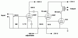
Here's an interesting (as in "different", not necessarily as in "looks good") 6V6 circuit: Single Ended (SE) 6V6 Tube Amplifier Schematic
Note both halves of a double-triode wired together and used as a single triode.
Also: the 6V6 has it's grid DC-coupled to the driver's anode and it's cathode is sitting up at 95V!
Different design philosophy to yours, though. It's using the 6V6 as a pentode with local and global feedback to straighten everything out.
- Status
- This old topic is closed. If you want to reopen this topic, contact a moderator using the "Report Post" button.
- Home
- Amplifiers
- Tubes / Valves
- How do you determine a driver stage?