DCD amplifier: new topology?
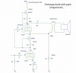
After some experimenting I decided to share this schematic with you, so that you can comment on it.
Also I would like to know if there are flaws in the design.
I build it already in 3 prototype flavours: 12bh7a-el34 d3a-el34 and d3a-807. All sounded really good.
How did it come to this schematic? It started with browsing on internet, and reading numerous stories about sound and tube amplifiers. After reading it looked to me that coupling C’s are unwanted; they have a lot (too much) influence on the sound.
So I decided to build a DC coupled Amp. I started with considering the Morrison Micro, but after I realized the dangers, and unwanted power-up conditions I moved on to a loftin-white schematic. After reading a lot, I somewhere along the line read about the DRD amplifier-topology. That seemed to me like a very fine schematic. But it uses large inductances , which where too expensive for me.
So I wondered if I could use a CCS in place of the coil. After asking some help from the more experienced builder/designers here on diyaudio, I learned that dsavitsk had considered building a similar concept. (cheap lunch) Unfortunately, he never build it. Learning about it, and the problems at power-on, I realized there had to be some changes made.
At the same time I read an excellent article about loop distortion.
Bay Area Tube Festival
I saw the Western Electric style- parafeed output, and decided that that would solve my problems, and make a superb output stage as well. (I saw it on Gary Pimms site too)
How does it work? The top CCS is set to the current chosen for the output tube. Because this is the only point wich is connected to the powersupply, and the current drawn is always the same, it acts as a stabilized power supply. Also, there is no (ac) signal flowing through the powersupply, only through the parafeed capacitor and the output transformer. That leads to the cathode of the output tube. There the ac current and dc current add up to the set current for the output tube.
Because the current used by the driver tube is lower than that, there has to be a bleeder resistor who has 2 functions; there is a constant, dc only current flowing through it, so it acts as a regulated voltage supply for the driver-tube, and it bleeds of all current which the driver tube circuit does’nt use.
The driver tube has its own CCS which is set to the current chosen for it. The anode is directly connected to the grid of the output tube. This sets the biasing voltage for the output tube, wich is: (Vanode driver) – (Vkathode outputtube).
Because the drivertube’s bias current is a constant, its cathode resistor determines its anode voltage, and because the bias for the output tube is dependant on that, also the anode voltage for the output tube.
The prototypes were all stable, no problems setting the correct voltages, and I experienced no drift after a few weeks.
If you want to build it for yourself, choose the setting resistors for the CCS’s as fixed resistors; they are not critical. Make the cathode resistor variable however, because with it, you set Va for the driver as well as the output tube. It is thus used to tune out the unavoidable differences between tubes, which is neccesary,even if they are the same model and brand.
The setting of the amplifier can be determined in 2 ways:
1: predict your optimal anode voltage by drawing the load line for the output tube. Than adjust the variable cathode resistor so that the measured Va reflects this.
2: put a sinus-input signal on the amplifier, and adjust it so the amplifier starts clipping. Than adjust the variable cathode resistor for minimal distortion, or symmetric clipping on a scope.
I called it "DCD amplifier": Direct-coupled Ccs Driven amplifier, (with a wink to the drd amp, with wich it has a lot in common) If someone is offended by the name or if anyone build an amplifier like this one, let me know.
The final version of this one is going to be build in a month or so; i’m waiting for the iron and the tubes. Its going to use a JJ-2a3-40 with a d3a driver, and AE-europe iron.
The prototype sounds really good, very dynamic, very good focus and depth. (its about 1 watt) Better than all the amplifiers I heard before. On the other hand: I never heard a really good single ended amp. So I have to build a standard design SE amp, or find someone in my neighbourhood who has one, to compare them.
Please feel free to comment on it any way you like. I want to know if i missed some obvious things, or maybe some more experienced designer sees ways to improve it.
Some measurements for the d3a-el34 prototype:
Va d3a: 27,3v pp; D=0,18%
Va el34: 195v pp; D=1,27%
V speaker(6ohm): 5,0v pp; D=1,3%-> approx 0,5 watt
Maybe the post is too long, and nobody wants to read it... and I defeated myself with wanting to give too much information, and to contribute something myself to the Tube community I love so much. We will see...
Greetings, Paul
After some experimenting I decided to share this schematic with you, so that you can comment on it.
Also I would like to know if there are flaws in the design.
I build it already in 3 prototype flavours: 12bh7a-el34 d3a-el34 and d3a-807. All sounded really good.
How did it come to this schematic? It started with browsing on internet, and reading numerous stories about sound and tube amplifiers. After reading it looked to me that coupling C’s are unwanted; they have a lot (too much) influence on the sound.
So I decided to build a DC coupled Amp. I started with considering the Morrison Micro, but after I realized the dangers, and unwanted power-up conditions I moved on to a loftin-white schematic. After reading a lot, I somewhere along the line read about the DRD amplifier-topology. That seemed to me like a very fine schematic. But it uses large inductances , which where too expensive for me.
So I wondered if I could use a CCS in place of the coil. After asking some help from the more experienced builder/designers here on diyaudio, I learned that dsavitsk had considered building a similar concept. (cheap lunch) Unfortunately, he never build it. Learning about it, and the problems at power-on, I realized there had to be some changes made.
At the same time I read an excellent article about loop distortion.
Bay Area Tube Festival
I saw the Western Electric style- parafeed output, and decided that that would solve my problems, and make a superb output stage as well. (I saw it on Gary Pimms site too)
How does it work? The top CCS is set to the current chosen for the output tube. Because this is the only point wich is connected to the powersupply, and the current drawn is always the same, it acts as a stabilized power supply. Also, there is no (ac) signal flowing through the powersupply, only through the parafeed capacitor and the output transformer. That leads to the cathode of the output tube. There the ac current and dc current add up to the set current for the output tube.
Because the current used by the driver tube is lower than that, there has to be a bleeder resistor who has 2 functions; there is a constant, dc only current flowing through it, so it acts as a regulated voltage supply for the driver-tube, and it bleeds of all current which the driver tube circuit does’nt use.
The driver tube has its own CCS which is set to the current chosen for it. The anode is directly connected to the grid of the output tube. This sets the biasing voltage for the output tube, wich is: (Vanode driver) – (Vkathode outputtube).
Because the drivertube’s bias current is a constant, its cathode resistor determines its anode voltage, and because the bias for the output tube is dependant on that, also the anode voltage for the output tube.
The prototypes were all stable, no problems setting the correct voltages, and I experienced no drift after a few weeks.
If you want to build it for yourself, choose the setting resistors for the CCS’s as fixed resistors; they are not critical. Make the cathode resistor variable however, because with it, you set Va for the driver as well as the output tube. It is thus used to tune out the unavoidable differences between tubes, which is neccesary,even if they are the same model and brand.
The setting of the amplifier can be determined in 2 ways:
1: predict your optimal anode voltage by drawing the load line for the output tube. Than adjust the variable cathode resistor so that the measured Va reflects this.
2: put a sinus-input signal on the amplifier, and adjust it so the amplifier starts clipping. Than adjust the variable cathode resistor for minimal distortion, or symmetric clipping on a scope.
I called it "DCD amplifier": Direct-coupled Ccs Driven amplifier, (with a wink to the drd amp, with wich it has a lot in common) If someone is offended by the name or if anyone build an amplifier like this one, let me know.
The final version of this one is going to be build in a month or so; i’m waiting for the iron and the tubes. Its going to use a JJ-2a3-40 with a d3a driver, and AE-europe iron.
The prototype sounds really good, very dynamic, very good focus and depth. (its about 1 watt) Better than all the amplifiers I heard before. On the other hand: I never heard a really good single ended amp. So I have to build a standard design SE amp, or find someone in my neighbourhood who has one, to compare them.
Please feel free to comment on it any way you like. I want to know if i missed some obvious things, or maybe some more experienced designer sees ways to improve it.
Some measurements for the d3a-el34 prototype:
Va d3a: 27,3v pp; D=0,18%
Va el34: 195v pp; D=1,27%
V speaker(6ohm): 5,0v pp; D=1,3%-> approx 0,5 watt
Maybe the post is too long, and nobody wants to read it...
and I defeated myself with wanting to give too much information, and to contribute something myself to the Tube community I love so much. We will see...Greetings, Paul
Attachments
Last edited:
DCD amplifier: new topology?
Definitely not. Alan Kimmel (and others) have described something very much like this: SRPP or Mu-Stage stabilized by CCSs. After nearly 100 years worth of vacuum tube R & D, the odds of anyone coming up with anything totally new and original are about the same as hitting the lottery.
Very interesting.
My only comment is I would worry about the wiper of R7 going open. if I were building it, R7 would be larger and paralleled with a fixed resistor, or substituted with an LED string.
Doug
Wiper is no immediate problem. Dissipation goes up, but is still limited by the upper ccs. And if your listening, and the sound vanishes, that will get your attention. Even if you pull the driver tube, it does nothing but give some extra dissipation in the output tube and bleeding resistor.
Well, it is new to me!Definitely not. Alan Kimmel (and others) have described something very much like this: SRPP or Mu-Stage stabilized by CCSs. After nearly 100 years worth of vacuum tube R & D, the odds of anyone coming up with anything totally new and original are about the same as hitting the lottery.
But seriously, this design has nothing to do with SRPP or Mu stage.
I was afraid that someone would say this, because if you draw 2 tubes above each other, a lot of people cry "SRPP" or something. But if you look at the schematic, you'll see that the cathode of the output tube is at a FIXED point, I mean its at a set voltage. So both stages (driver and output) operate independently.
With both SRPP and MU stage, the cathode of the upper tube swings up and down with the anode of the lower tube. Thats because in both schedules the upper tube acts more or less like a CCS, and does approx. the opposite of the lower tube.
My goal was not trying to design something new, but rather came out like this when I defined my design parameters. If in the end comes out that a different topology sounds better, for a price I can afford, i'll probably end up with that one.
And of course you are right. In the almost 100 years of tube tech, pretty much everything has been tried. But to say up front, "everything has been tried, so lets not try and experiment, and stick with a well known design", well thats not my cup of tea. If everybody thought this way, nothing new would ever be invented. Furthermore, if nothing else, I learned a lot out of it.
Member
Joined 2009
Paid Member
I'm seeing a two stage DC coupled amplifier. CCS plate load on the input tube DC coupled to a CCS loaded parallel fed output stage with unbypassed cathode resistor, transformer primary return to the actual cathode. Cool amp, voltages sure set up a lot easier than with choke load on the input tube.... but wheres the CCS coupling - its direct coupled input plate to driver grid.
Shane
Shane
Very nice. Would you be willing to post your final schematic and power supply? I may try it, I have several d3a's that need a home....maybe I'll try with a 307.
Sure! I'll post it here, but it may take some days, i'm very busy at the moment...
I'm seeing a two stage DC coupled amplifier. CCS plate load on the input tube DC coupled to a CCS loaded parallel fed output stage with unbypassed cathode resistor, transformer primary return to the actual cathode. Cool amp, voltages sure set up a lot easier than with choke load on the input tube.... but wheres the CCS coupling - its direct coupled input plate to driver grid.
Shane
You are right of course. I took some liberty because the name sounded good, and the schematic resembles the DRD amplifiers a bit.
Voltages are indeed easy to set up, mine is set up over a year ago, and it still sounds perfect. I want to measure the settings for over a few months now, but can't seem to find the time (or maybe i'm a bit lazy)
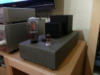
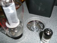
Here some pics...
Paul
Attachments
Sure! I'll post it here, but it may take some days, i'm very busy at the moment...
Thanks! And no rush, I have 4 or 5 projects ahead of any new ones, and a 2.5 year old who takes up most of my hobby time. Anytime in the next couple of years is fine ;-)
- Status
- This old topic is closed. If you want to reopen this topic, contact a moderator using the "Report Post" button.
- Home
- Amplifiers
- Tubes / Valves
- DCD power amplifier: 2A3/d3a CCS coupled: new topology?