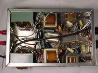
I just picked up an Akai M8 R2R. I replaced the 'lytics and coupling caps, chopped the box down, turned it upside down and tossed them back in it. It is a darn neat little amp (monoblocks with choke filtered supplies!), and the chassis got me to thinkin'.
I am still pondering a bi-amped open baffle speaker setup. This little guy has preamp outputs. How happy would it be driving both it's output section and my PP 6V6 amp (50K input impedance) with some simple passive filters? It has much more gain than I need, so insertion loss isn't a problem. I was thinking of biamping with SS on the bottom, but SE on top and PP on bottom sounds like much more fun.
The second problem is that it doesn't sound as good as my El Cheapo (Eli Duttman's PP 6V6 triode amp). I'm glad, because the El Cheapo is huge (mine is choke input and motor runs) and took plenty of time and $$. But, if I'm going to use this thing on fullrangers, I need it to sound better than it does (it sounds fine, but not good enough). Would some parts upgrades and a conversion to triode cut it, or do I need to consider building in a new circuit? I wouldn't be opposed to doing something like an RH84, but I'd need to put a preamp in front of it. The chassis allows some flexibility in that regard. But, if the rebuild gets too complicated, I may as well sell these guys and build the 12B4 preamp I as thinking about (though then I'd still have SS on the bottom. . .)
So A: Will I be happy biamping with the preouts
and
B: Do I tweak the stock circuit, or start anew?
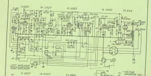
I couldn't find an online schematic to post, but I figured a few folks might be familiar with them. It's a fairly typical EF86 (not using) 12AX7, SEP EL 84 R2R amp. I'll run to a copy shop and scan the schematic if folks want to see it.
Paul
Wild Burro Audio Labs - DIY Full Range Speakers
I am still pondering a bi-amped open baffle speaker setup. This little guy has preamp outputs. How happy would it be driving both it's output section and my PP 6V6 amp (50K input impedance) with some simple passive filters? It has much more gain than I need, so insertion loss isn't a problem. I was thinking of biamping with SS on the bottom, but SE on top and PP on bottom sounds like much more fun.
The second problem is that it doesn't sound as good as my El Cheapo (Eli Duttman's PP 6V6 triode amp). I'm glad, because the El Cheapo is huge (mine is choke input and motor runs) and took plenty of time and $$. But, if I'm going to use this thing on fullrangers, I need it to sound better than it does (it sounds fine, but not good enough). Would some parts upgrades and a conversion to triode cut it, or do I need to consider building in a new circuit? I wouldn't be opposed to doing something like an RH84, but I'd need to put a preamp in front of it. The chassis allows some flexibility in that regard. But, if the rebuild gets too complicated, I may as well sell these guys and build the 12B4 preamp I as thinking about (though then I'd still have SS on the bottom. . .)
So A: Will I be happy biamping with the preouts
and
B: Do I tweak the stock circuit, or start anew?
I couldn't find an online schematic to post, but I figured a few folks might be familiar with them. It's a fairly typical EF86 (not using) 12AX7, SEP EL 84 R2R amp. I'll run to a copy shop and scan the schematic if folks want to see it.
Paul
Wild Burro Audio Labs - DIY Full Range Speakers
They are tube rectified: 6X4's. I know I need to get a schematic up. What do you think about the preamp out/passive filter idea?
Paul
Wild Burro Audio Labs - DIY Full Range Speakers
Paul
Wild Burro Audio Labs - DIY Full Range Speakers
They are tube rectified: 6X4's.
So much for the better "sand" diode idea.

What do you think about the preamp out/passive filter idea?
I find the possibilities of impedance mismatches galore disturbing. Buffering the passive blocks, as Marchand does in his tubed crossovers, seems better to me.
I need it to sound better than it does (it sounds fine, but not good enough). Would some parts upgrades and a conversion to triode cut it, or do I need to consider building in a new circuit?
You could change things along the lines of the RH84. FWIW, I'd add some GNFB to linearize the O/P trafo. Switching to LED bias for the voltage amplifier goes hand in glove with that concept. LR8 regulating g2 B+ is another possible tweak to the RH84 concept.
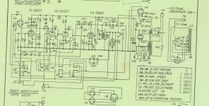
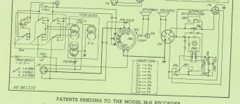
Since an M8 schematic is nowhere to be found on the web, I figured I'd toss one up here. I cropped it into three parts so I could post it at the full resolution of the scan. Let me know what you think of the circuit, and especially the preamp ouputs capabilities.
Paul
Wild Burro Audio Labs - DIY Full Range Speakers
Paul
Wild Burro Audio Labs - DIY Full Range Speakers
Attachments
S
I find the possibilities of impedance mismatches galore disturbing. Buffering the passive blocks, as Marchand does in his tubed crossovers, seems better to me.
Eli, I've already got more tubes than I need in the amps. What about building a buffer into them that could drive anything? Maybe volume control>buffer circuit>preamp outputs>RH84 etc?
Eli, I've already got more tubes than I need in the amps. What about building a buffer into them that could drive anything? Maybe volume control>buffer circuit>preamp outputs>RH84 etc?
PJ,
That makes sense to me. The buffered volume control will be master. Set and forget volume adjustments on each amp are needed for "seamless" integration.
I can't say I've gone over the schematic with a fine toothed comb, but I didn't notice NFB of some kind around the EL84.
The 6AR5 is a small power pentode that draws 400 mA. of heater current. Right there, you have the heater current for 1 section of an ECC99 wired as a cathode follower, which is a kick butt buffer. Set alternate sections up in each channel, to allow for flip/flop when service life ends. You'll go YEARS between outright replacement. In the R2R, the 6AR5 is serving as the bias/erase oscillator. Recycle the EF86 sockets for the ECC99s.
The second problem is that it doesn't sound as good as my El Cheapo (Eli Duttman's PP 6V6 triode amp).
My main amplifier for nearly the last two years has been a pair of these that I stripped down and rebuilt on a new chassis. The design is very simple; an EF86 driving a SE 6V6 (pentode) in each channel. I used all the original iron. To keep the octal theme (6V6), I used brown-base 6X5s rather than the original 6X4s. Each channel is lined up side-by-side on the chassis with the EF86s in the front, followed by the 6V6s and 6X5s.
The sound quality of these amps is extremely good; you just have to get all the tape recorder junk out of the way. You also have to give that 12AD7 (12AX7) the boot. The original design used the 12AD7 to drive the output, but the EF86 absolutely decimates it in this application. Where the triode is dull and lifeless, the EF86 carries nuances and transparency that can almost overwhelm. As it has turned out, my speakers aren't quite up to the task. I have spent many late nights listening to these through Grados, astounded by the exquisite tonality of these inexpensive amps. The only other amps I've experienced this with are my 211 SETs.
Attachments
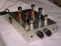
Now that is pretty! That snug fit is right up my alley. I'm trying to avoid a new chassis though. My wife and I both actually like the look of the M8's as is! I'd love to see your schematic. I'd consider 6AQ5's as the sockets would work out.
Heater current for the pre isn't a problem at all. In addition to the 6AR5, I assume I'll ultimately end up loosing another triode. I don't think I need a pre and two halves of a dual triode to drive an EL84.
With my wimpier sources, the EC has just enough gain. I'm afraid a cathode follower and the possibility of a passive filter might be be problematic. How about a 12B4 pre like I was asking about last month? I couldn't fit a fancy power supply, and I don't have as much B+ available as some folks use. I do intend to lose the 12AX7 as soon as possible, but it may be towards the end of this project. It is a speaker project afterall . . . FWIW, I'm exploring the possibility of using some sort of Behringer DSP to do the woofer crossover. They tend to have input impedances from 10-25K unbalanced, so the pre would need to drive that along with the RH84 or whatever I end up doing for the top amp.
Paul
Wild Burro Audio Labs - DIY Full Range Speakers
Now that is pretty! That snug fit is right up my alley. I'm trying to avoid a new chassis though. My wife and I both actually like the look of the M8's as is! I'd love to see your schematic. I'd consider 6AQ5's as the sockets would work out.
Heater current for the pre isn't a problem at all. In addition to the 6AR5, I assume I'll ultimately end up loosing another triode. I don't think I need a pre and two halves of a dual triode to drive an EL84.
With my wimpier sources, the EC has just enough gain. I'm afraid a cathode follower and the possibility of a passive filter might be be problematic. How about a 12B4 pre like I was asking about last month? I couldn't fit a fancy power supply, and I don't have as much B+ available as some folks use. I do intend to lose the 12AX7 as soon as possible, but it may be towards the end of this project. It is a speaker project afterall . . . FWIW, I'm exploring the possibility of using some sort of Behringer DSP to do the woofer crossover. They tend to have input impedances from 10-25K unbalanced, so the pre would need to drive that along with the RH84 or whatever I end up doing for the top amp.
Paul
Wild Burro Audio Labs - DIY Full Range Speakers
PJ,
A 12B4 preamp can drive 10 KOhms, but paralleling a DSP and an EC is making the net load too low.
Let's see, lose the pilot lamp, use only 1 section of a 'T7 for the RH84 and tie the EF86 filament winding off. That would leave enough heater "juice" for an ECC99's sections to serve as a voltage amplifier and CF. The ECC99's high gm yields a CF whose O/P impedance is in the neighborhood of 100 Ω. That's low enough to feed a net 5 KOhm load, with aplomb.
I tweaked values quite a bit when I was finalizing this amplifier. If I can find my notes, I'll post the details. Meanwhile, here's a link to the Mullard 3-3 amplifier that it's based on. Build this circuit using the Akai/Roberts parts and you're 95% home.
Mullard 3-3 Three Watt Amplifier
Mullard 3-3 Three Watt Amplifier
I have a total of 6 of these (1 pair in a tape deck i want to restore).
EF86 > EL84 was what i was going to do.
dave
They are a neat chassis to build on. The OPTs are almost exactly the same size as those in the Sony TC500. But, you've got the dual mono supply, chokes and a stock chassis that is useable (I suppose one could use the TC500 chassis, but I wouldn't). I'm not sure what I'll do for input jacks. If only there was enough space for motor runs!
I've seen both you and ChrisB mention the EF86>EL84. I assume you are thinking of RH84 style feedback? Any circuits to share?
Paul
Wild Burro Audio Labs - DIY Full Range Speakers
PJ,
A 12B4 preamp can drive 10 KOhms, but paralleling a DSP and an EC is making the net load too low.
The DSP will actually be in front of the EC, which would be powering the woofers. The pre would drive the RH84 (probably 100K) and the DSP. If I use the DSP 8024 (have to find it used), it would have an input impedance of 25Kohms. I'd be looking at a 20K load together. Even if I end up with a 25K pot in front of the SE amp, I should be fine 12B4. I could not drive the DCX2496 though, as it is 10K unbalanced all by itself.
Triode Kingdom, Now I think I remember you writing about your 3-3 project. I'll have to do some searching.
Paul
Wild Burro Audio Labs - DIY Full Range Speakers
I plan on reconfiguring the existing front panel holes for I/O for a 2-input integrated and get Chris to build a couple wooden sleeves for them.
Attached is as much as exists for the current RH84 based monobloks. I don't think it is completely up-to-date. Next build will not be parafeed and likely will use EF86 in pentode.
dave
Attached is as much as exists for the current RH84 based monobloks. I don't think it is completely up-to-date. Next build will not be parafeed and likely will use EF86 in pentode.
dave
Attachments
PJ,
Let's pause and take inventory. Each monoblock chassis has 3X 9 pin and a 7 pin socket available for signal tubes. The 6X4 rectified PSU is good for 60 mA. of B+.
Regardless of the "final" chosen, 'BQ5 or 'AQ5, 40 mA. of B+ will get "eaten". That leaves 20 mA. for small signal stuff.
If you go the RH84 route, a 6AB4 in the 7 pin socket and an EL84 leaves 2X 9 pin sockets for preamp duty. If you go TK's tweaked 3-3 route, a 6AQ5 in the 7 pin socket and an EF86 in a 9 pin socket leaves 2X 9 pin sockets for preamp duty too. TK used a 6V6. Other than screen grid fragility, the 6AQ5 is a 6V6 in a 7 pin mini bottle. Deal with g2 fragility by regulating g2 B+ with a LR8 IC. Regulating g2 B+ also improves linearity.
If a few more mA. of B+ are necessary for both power and preamp purposes, switching to SS B+ rectification along with a smallish 1st filter cap. will get the job done. A small 1st filter cap. reduces I2 heating in the rectifier winding at the expense of reduced rail voltage. Some extra B+ current becomes available as a consequence of less heat. The lower forward drop in SS diodes compensates for the voltage loss due to 1st cap. value decrease.
I see that 60ma all over the schematic, but I don't understand how the amps aren't drawing more. Is that 6AR5 being run substantially differently from the datasheet's 32-35ma plate current? It must be, otherwise, the 12B4 would draw about the same, and I'd be using a couple ma less B+ current than the stock amp.
I know it isn't as ideal as an EF86, but I'm leaning towards using half of a 12AT7 in an RH84 circuit for each monoblock. I've amassed a few good pairs of 'T7's, and it is just easy to use the same tube. I'd wire one monoblock to use each half, so I could swap them side for side.
thanks for all your help gents,
Paul
Wild Burro Audio Labs - DIY Full Range Speakers
I'm planning to go ahead with the 12B4/RH84 combo and see if it works. I ended up getting a DSP with an even lower input impedance, so I'm going to buffer it with an opamp. I'm thinking the pre will end up driving a combined load of 16K or so. It depends on where I set the input impedance of the buffer.
I think (hope) the power transformer will be fine. I am going to draw a bit more off the HV winding than is spec'd, but I'll be using half an amp less filament current. I also assume that if the PT can put out 60ma of HV on 50hz power, that it can easily exceed that on 60hz. If it gets too hot, I'll have to come up with another plan.
Paul
Wild Burro Audio Labs - DIY Full Range Speakers
PJ,
The 100% safe way to squeeze a few extra mA. of B+ out of the power trafo is to switch to SS rectified B+. The 1st cap. in the CLC filter is sized just large enough to keep the rail voltage up. A small 1st cap. drops the rail voltage, but the lower forward drop in SS diodes compensates. A small 1st cap. makes the conduction angle larger and heating is reduced.
You've already built a "cockeyed bridge". Build 2 more.
Use the rectifier filament winding to power the 12B4. Betcha that power trafo stays cool.
- Status
- This old topic is closed. If you want to reopen this topic, contact a moderator using the "Report Post" button.
- Home
- Amplifiers
- Tubes / Valves
- Akai M8 rebuild/restore/will-this-work?