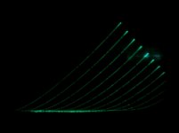
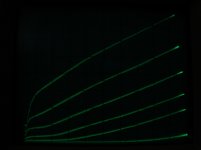
I purchased some cheap JAN 1619 tubes and I could only find the pentode curves. I traced the triode curves using my oscilloscope and a digital camera. Picture is attached. I hooked up a 300v ct transformer into a bridge rectifier to get a Plate driver signal. Connected a 10 ohm resitor to the cathode and G2 to the plate (with 100 ohm resistor). I used my bench DC supply to set the control grid voltage and took a picture with each voltage setting. I brought the pictures into the PC and combined them into one.
I tried tracing the UL curves but my setup does not seem to work. I tried tracing them with an edcor SE transformer with 42% taps. The do not come out clean. The trace look very linear on the positive slope of the drive signal but on the negative sloped side they look distorted.
I want to find the optimal tap value for the Jan1619 tube.
Does anybody know the proper setup to trace the UL curves?
Attachments
Hi, connecting G2 (screen) to the plate will give you triode operation. That is also what your curve traces show. To trace pentode operation, you will need to tie G2 to a fixed supply. To trace the UL plate curves, you will need to hook up G2 to a fixed divider off the plate. The 42% taps on your transformer will work nicely. Also, you should pu the 10 resistor in the plate, otherwise you are measuring plate+screen current. BTW, 42% will be pretty optimal. But then again, what is optimal? it is just a tradeoff between power and distortion - what are your goals for each?
hey-Hey!!!,
I've run the 1619 U-L with two types of OPT's. B+ of ~310 in both cases( it was the same amp, just swapped in different OPT's ). First off was the Z565 from a Dynaco SCA35. That one has taps near 25%. It worked very well. Next was a far larger one, a Peerless S265 with U-L taps added at 20, 30 and 40% across the anode winding. The 1619 liked the lower percentages much better.
This was early in my U-L experiments, and I've since learned a bit more. From a rather unlimited PoV, moving towards triode is a good thing, the effective plate impedance can be reduced substantially from pentode mode. However, no tube is anything like 'unlimited'. As we move the g2 along the anode coil, maximum conduction g2 voltage drops. This effect has important effects for the load choice...make it too steep( low numeric ) or too high a U-L tap %-age location and the load line runs into the zero-bias limits pretty quickly. Trading load, tap location and tube characteristics is a much more interesting game with U-L...")
Now on to type 1619; maximum g2 voltage puts some limits on maximum conducted current( how far up the scale the g1=0 line goes on the y, current axis ). Then we've got a practical 12-13 W limit on plate dissipation because we will never know when someting inside the steel bottle is too hot. These things combine to point towards a low tap percentage combined with a substantial load( high numeric ) to get the best performance from this one.
cheers,
Douglas
I've run the 1619 U-L with two types of OPT's. B+ of ~310 in both cases( it was the same amp, just swapped in different OPT's ). First off was the Z565 from a Dynaco SCA35. That one has taps near 25%. It worked very well. Next was a far larger one, a Peerless S265 with U-L taps added at 20, 30 and 40% across the anode winding. The 1619 liked the lower percentages much better.
This was early in my U-L experiments, and I've since learned a bit more. From a rather unlimited PoV, moving towards triode is a good thing, the effective plate impedance can be reduced substantially from pentode mode. However, no tube is anything like 'unlimited'. As we move the g2 along the anode coil, maximum conduction g2 voltage drops. This effect has important effects for the load choice...make it too steep( low numeric ) or too high a U-L tap %-age location and the load line runs into the zero-bias limits pretty quickly. Trading load, tap location and tube characteristics is a much more interesting game with U-L...
Now on to type 1619; maximum g2 voltage puts some limits on maximum conducted current( how far up the scale the g1=0 line goes on the y, current axis ). Then we've got a practical 12-13 W limit on plate dissipation because we will never know when someting inside the steel bottle is too hot. These things combine to point towards a low tap percentage combined with a substantial load( high numeric ) to get the best performance from this one.
cheers,
Douglas
Thank you both.
I have attached more pictures. One is the digitized triode curves.
I have drawn two PD curves, one for the Plate PD only and one of Plate plus Screen.
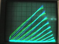
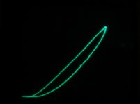
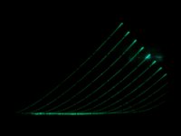
Another shows the problem I reported on my UL setup. The picture is for a single g1 voltage, see the loop I am referring to. The loop exists with our without load and with both the SE Edcor transformer and a cheapo 7010. I cheated and erased the lower portion of the loop and produced a combination graph of 25,35 and 50 percent taps from the 7010 transfomer.Colors are in that order from top to bottom. I wonder if these are valid curves. I also have heard that lower taps would suit the 1619 better, this is why I wanted to check.
Douglas, soundwise, have you had better experience in triode mode or UL?
Alfredo
I have attached more pictures. One is the digitized triode curves.
I have drawn two PD curves, one for the Plate PD only and one of Plate plus Screen.
Another shows the problem I reported on my UL setup. The picture is for a single g1 voltage, see the loop I am referring to. The loop exists with our without load and with both the SE Edcor transformer and a cheapo 7010. I cheated and erased the lower portion of the loop and produced a combination graph of 25,35 and 50 percent taps from the 7010 transfomer.Colors are in that order from top to bottom. I wonder if these are valid curves. I also have heard that lower taps would suit the 1619 better, this is why I wanted to check.
Douglas, soundwise, have you had better experience in triode mode or UL?
Alfredo
Attachments
hey-Hey!!!,
I like U-L mode better than triode. There are a few likely suspects, one being power output. Even with sensitive speakers, a bit more headroom is quite useful and 1619 in class A PP triode does not make so much. Also, what I'd characterize as leading edge sonics, like the pluck of a string did a better job with U-L.
Since you're on this path, let me also suggest type HY69. It is 807-ish with a thoriated tungsten cathode. Nice to look at and listen to. Also seems to prefer 20-30% U-L tapping, at lest to my ears.
cheers,
Douglas
Does anybody know the proper setup to trace the UL curves?
Sure
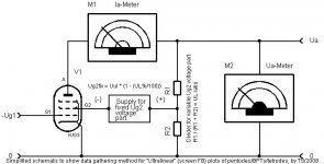
Attached you will find what essentially I use myself - okay, shown somewhat simplified here, but you sure will get the idea. All necessary formulae are given. Depending on the tube you want to measure, be sure to have "enough" current running down the R1,R2 series chain divider, say, about 3x of what you expect (or know) to be the peak Ig2 requirement (within the a->g2 current takeover region) of the TUT.
All the UL plots on my homepage were done using essentially the same principle. Example here.
Regards,
Tom
Attachments
Last edited:
Sure
Attached you will find what essentially I use myself - okay, shown somewhat simplified here, but you sure will get the idea. All necessary formulae are given.
Thanks Douglas, I am definitely pursuing UL.
Tom,
For the fix UL voltage portion formula, what is Uul AND UL?
Alfredo
Hi Alfredo,
Uul is the "ultralinear voltage", meaning the iddle voltage you want your tube to run at, hence the voltage where Ua=Ug2 (or Ea=Eg2, if you prefer). Never mind in real world (using an OPT w/ UL taps) Ea probably will be a very few Volts less than Eg2 due to the additional ohmic (copper-) resistance between the UL tap and the anode tap of the primary of the OPT.
UL% is just the UL ratio given in percents, as usual. Counting from B+, 0% means g2 to B+ (pure pentode operation), 100% means g2 to anode (pseudotriode operation).
Regards,
Tom
For the fix UL voltage portion formula, what is Uul AND UL?
Uul is the "ultralinear voltage", meaning the iddle voltage you want your tube to run at, hence the voltage where Ua=Ug2 (or Ea=Eg2, if you prefer). Never mind in real world (using an OPT w/ UL taps) Ea probably will be a very few Volts less than Eg2 due to the additional ohmic (copper-) resistance between the UL tap and the anode tap of the primary of the OPT.
UL% is just the UL ratio given in percents, as usual. Counting from B+, 0% means g2 to B+ (pure pentode operation), 100% means g2 to anode (pseudotriode operation).
Regards,
Tom
Uul is the "ultralinear voltage", meaning the iddle voltage you want your tube to run at, hence the voltage where Ua=Ug2 (or Ea=Eg2, if you prefer).
Thanks, now I understand it.
On your setup, do you use pulsed drive signals? Are these from a PC source or a dedicated hardware circuit? I am manually varying g1. I need to build a staircase drive for G1. For me the plate drive works well with the Variac and a bridge rectifier.
By the way... Do you have UL curves for the PL36?
Alfredo
Hi Alfredo,
I am using only a few PSUs and DVMs plus the graphing functions of good old Excel 2k for visualization.
Not necessarily - just free your mind from evil staircase thinking. For example, have a look at the tracer approach from Monsieur Yves Monmagnon (nick YvesM here), see his curves tracer. I bet Yves can come up with some cool & KISS ideas how to do UL plots, too.
Yes, but rather likely not for the operation point *you* want a plot for BTW, German broadcasting and studio gear supplier Klein + Hummel had an EL36 PP/UL amp in their consumer product line, called the Telewatt VS70, for schematics etc look here.
Regards,
Tom Schlangen
On your setup, do you use pulsed drive signals? Are these from a PC source or a dedicated hardware circuit?
I am using only a few PSUs and DVMs plus the graphing functions of good old Excel 2k for visualization.
I am manually varying g1. I need to build a staircase drive for G1.
Not necessarily - just free your mind from evil staircase thinking. For example, have a look at the tracer approach from Monsieur Yves Monmagnon (nick YvesM here), see his curves tracer. I bet Yves can come up with some cool & KISS ideas how to do UL plots, too.
By the way... Do you have UL curves for the PL36?
Yes, but rather likely not for the operation point *you* want a plot for
BTW, German broadcasting and studio gear supplier Klein + Hummel had an EL36 PP/UL amp in their consumer product line, called the Telewatt VS70, for schematics etc look here.Regards,
Tom Schlangen
Last edited:
Hi Douglas,
Indeed, it is critical. There are a few small "series" of UL plots for the same tube on my homepage, with (seemingly...) only slight variations of the UL OP, f.e, have a look at those plots:
ECL82/6BM8, PCL82/16A8 pentode section with 30% UL at Eg2 = 170V
ECL82/6BM8, PCL82/16A8 pentode section with 20% UL at Eg2 = 200V
ECL82/6BM8, PCL82/16A8 pentode section with 30% UL at Eg2 = 200V
ECL82/6BM8, PCL82/16A8 pentode section with 20% UL at Eg2 = 230V
available here.. Such a small series of plots is most interesting to get a "feeling" for what is going on when changing the UL voltage (sorry, I have no better name for Ea=Eg2 in this certain case of screen grid FB aka UL OP) and/or the UL% ratio, even when changes are rather small. Thinking about it, this is just another reason for me to dislike UL OP, especially for SE power stages ...
Regards,
Tom Schlangen
hey-Hey!!!,
Tom has just noted the critical bit when considering U-L, the starting point is *VERY* important.
Indeed, it is critical. There are a few small "series" of UL plots for the same tube on my homepage, with (seemingly...) only slight variations of the UL OP, f.e, have a look at those plots:
ECL82/6BM8, PCL82/16A8 pentode section with 30% UL at Eg2 = 170V
ECL82/6BM8, PCL82/16A8 pentode section with 20% UL at Eg2 = 200V
ECL82/6BM8, PCL82/16A8 pentode section with 30% UL at Eg2 = 200V
ECL82/6BM8, PCL82/16A8 pentode section with 20% UL at Eg2 = 230V
available here.. Such a small series of plots is most interesting to get a "feeling" for what is going on when changing the UL voltage (sorry, I have no better name for Ea=Eg2 in this certain case of screen grid FB aka UL OP) and/or the UL% ratio, even when changes are rather small. Thinking about it, this is just another reason for me to dislike UL OP, especially for SE power stages ...
Regards,
Tom Schlangen
I am using only a few PSUs and DVMs plus the graphing functions of good old Excel 2k for visualization.
Tom, I assume you are only getting values up to the Plate dissipation and then estimating the points beyond the plate dissipation?
Yes, but rather likely not for the operation point *you* want a plot for
I asked about the PL36 curves because I have some and have been reading the "poor mans 300" thread that mentions some UL usage but I did not find any details.
On the schematic referenced, is there a mention of the UL tap? I can see the B+ voltage but cant read the rest (no german)
Is there any reference to it?Thanks
Alfredo
hey-Hey!!!,
Tom has just noted the critical bit when considering U-L, the starting point is *VERY* important. U-L curves will vary depending on the B+, and of course the tap location...
Point taken, I was thinking a B+ of 300, very similar to what you have done with the 1619. I see you did a PP with Ra-a of 8K. Have you done a UL SE?
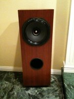
I know the tubes don't look that great as they are metal. There aren't many threads about the 1619 and a few i have read mention that some people like the triodded sound over a 45 (replacement with adaptor) and the 45 is supposed to sound very nice. I would play the ugliness of the tube, I have a theme for the AMP. Stealth 1619 SE. Everything flat black
Thanks
Alfredo
Point taken, I was thinking a B+ of 300, very similar to what you have done with the 1619. I see you did a PP with Ra-a of 8K. Have you done a UL SE?
I know the tubes don't look that great as they are metal. There aren't many threads about the 1619 and a few i have read mention that some people like the triodded sound over a 45 (replacement with adaptor) and the 45 is supposed to sound very nice. I would play the ugliness of the tube, I have a theme for the AMP. Stealth 1619 SE. Everything flat black
Thanks
Alfredo
hey Alfredo,
No SE, I don't like it much. Also built at 10k a-a, but that is a small difference. Your amp design sounds good, not that I'd consider any tube ugly...
cheers,
Douglas
hey Alfredo,
No SE, I don't like it much. Also built at 10k a-a, but that is a small difference. Your amp design sounds good, not that I'd consider any tube ugly...
cheers,
Douglas
I just received a handful of IXCP10M45's and i will do some testing with the ccs parafeed on the output tube. I have been prototyping and testing a few configurations for the 1619. Traditional SE and CCS self inverting PP. Without doing any real analysis the CCS PP appears to have some promise. Still low output power but all Class A. The experience with my efficient full range speakers is that anything over 10 Watts I never get to use. I finished recently a 7591 in PP that puts out around 35 Watts and I can only listen to it with the volume pot all he way down. My wife made me choose just one set of speakers... I kept the fullrange as I build them and took convincing (they are large
) the others are boxed in the attic.I will contact Edcor to see if they can make the GX series PP with a low UL tap for a decent cost. I think they have very good prices.
Thank you for all the feedback.
Alfredo
Attachments
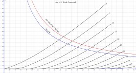
Was able to get some new curves using Tom's proposed setup but still using a rectified signal for the plate voltage.
Tom, the only way I was able to get current going to the tube was by inverting the polarity of the supply for Fixed Ug2.
Did plots for 42% and 20%. I missed a g1 step closed to the bottom of the 42% plot. Seems to be that both appear to have too much nonlinearity under lower Plate voltages. I played with voltage dividers with total resistans from 50K to 1meg. Didn't see much improvements on the plot kinks on the lower Plate voltages.
I like the look of the triode curves much more than the UL curves. I guess I can live with lower ouput power.
Alfredo
Attachments

Hi Alfredo,
Not necessarily - just free your mind from evil staircase thinking. For example, have a look at the tracer approach from Monsieur Yves Monmagnon (nick YvesM here), see his curves tracer. I bet Yves can come up with some cool & KISS ideas how to do UL plots, too.
I'm curious about this, how does it work if not with a staircase voltage? I can't figure it out from the schems alone, or the brief description.
Last edited:
- Status
- This old topic is closed. If you want to reopen this topic, contact a moderator using the "Report Post" button.
- Home
- Amplifiers
- Tubes / Valves
- Help with setup to trace UL curves