Wow Humming, that is sensational! ITEAD Studio 2Layer Green PCB 10cm x 10cm Max 10 boards for $19.95! and the reviews are all very good. Most places I have looked at the setup charges alone are more than that.
Tony.
Tony.
First of all, thank you for giving your nice board design to the community.
I can see from the photos that you are using regular pots for the bias? According to the schematic, if (when) a pot scraper lifts or gets dusty, you lose bias on this tube (=bang )
)
You should really change to multi turn cement pots, or change the way bias is applied.
I can see from the photos that you are using regular pots for the bias? According to the schematic, if (when) a pot scraper lifts or gets dusty, you lose bias on this tube (=bang
)You should really change to multi turn cement pots, or change the way bias is applied.
First of all, thank you for giving your nice board design to the community.
I can see from the photos that you are using regular pots for the bias? According to the schematic, if (when) a pot scraper lifts or gets dusty, you lose bias on this tube (=bang
You should really change to multi turn cement pots, or change the way bias is applied.
First, you are welcome.
Second, thank you for your comment.
I do have a question. What makes a multi-turn pot more robust than a standard 270°-300° pot?
The actual pots used in the system are Mil-Spec parts, but I am curious as to why the multi-turn pots are better.
AFAIK, they dont have a scraper that relies on the spring tension to make contact. This spring inside loses tension over time. It is more like a "full-body" contact of a conductive piston (the screw thingie) in conductive plasic cement. I am sure others can explain it better than me. By being 10 turns end to end, they are much less touchy to adjust.
On the other hand, I have only seen them in PCB mount version.
On the other hand, I have only seen them in PCB mount version.
First time builder.
I have been interested in tube amps for a while now, want to know what the buzz is about.
I have chosen this KT88 as my first build, my two reasons for this choice are.
First the documentation is incredible. Second is this is what i would consider middle of the road complexity tube project.
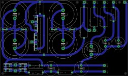
I will have more questions later, but for now i am starting with the power supply. I have done the layout for it in eagle 6.5.0 and attached. I made the board with all traces on the bottom. This way it works well with a LPKF mill or etching. I would appreciate you the veteran tube community to give your feedback on this young pups first amp build.
My main concern is that my gnd path is to long, I am thinking of soldering a wire from the gnd of C1 to the gnd of C11.
Thank you for your time!!!
I have been interested in tube amps for a while now, want to know what the buzz is about.
I have chosen this KT88 as my first build, my two reasons for this choice are.
First the documentation is incredible. Second is this is what i would consider middle of the road complexity tube project.
I will have more questions later, but for now i am starting with the power supply. I have done the layout for it in eagle 6.5.0 and attached. I made the board with all traces on the bottom. This way it works well with a LPKF mill or etching. I would appreciate you the veteran tube community to give your feedback on this young pups first amp build.
My main concern is that my gnd path is to long, I am thinking of soldering a wire from the gnd of C1 to the gnd of C11.
Thank you for your time!!!
Attachments
I have built the Williamson but I can't remember the bias settings I used. I don't recall them being critical, they didn't need much. FWIW I tried pentode, ultra-linear and triode outputs each with feedback and without. I preferred triode regardless. between 6 and 14dB global feedback was sufficient. Cathode follower drivers get more power but without is good within its limits.
I've read through the whole thread and there is no comment about what bias the KT88s are set to.
In the original post the builder said that the amp has 505 volts on the plates of the KT88s and is idling them at 28 watts. Simple math indicates that the output tubes are therefore biased at 55 mA each. This is close to the manufacturer's recommendation of 50 mA when used in fixed biased push-pull ultralinear mode, as is the case with this amp (again, according to the original post). See page 4 in the attached Genalex datasheet.
As John65b posted earlier, it's a good idea not to run the KT88 at more than 75% - 80% of its maximum dissipation rating of 42 watts, which would equate to a bias current of about 65 mA maximum with a 505 volt B+ supply. So anything in the 50 - 65 mA range should be OK if you build the amp as the original poster described.
I hope this helps.
Attachments
Hi. I'm building this circuit as 2 mono-blocks with a choke PSU. It's been a long time but is there any chance of getting the circuit diagram files please?
I've tried a couple of online diagramming tools but can't get symbols for the output and power transformers.
Thanks!
I've tried a couple of online diagramming tools but can't get symbols for the output and power transformers.
Thanks!
Question regarding Power Transformer
Hello,
I have never build a Push-Pull amp and this one is very atractive.I have a Power Transformer that has an output os 400V@500 mA for B+ and 70V@100 mA for grid voltage.I want to use it for both channels.
My concern is about - 83V grid voltage....can my Power Transformer feed 4xKT88 grids tubes with only 100 mA?What is the current draw of grid?
Regards,
Hello,
.can my Power Transformer feed 4xKT88 grids tubes with only 100 mA?What is the current draw of grid?
Regards,
Your KT88's should take no (zero) grid current so the only bias current is through perhaps your bias potentiometers.
Frank
Thanks Frank1 for your reply , that is good news for me.
Another question regarding the volume pot for this amp..in the interconects mode I see that it was use some input transformers & 10K pot.What will be another suitable solution for volume pot without those input transformers :
1)a 10K pot in front of input
2)a 500 K pot by replacing R1
3)a 10 K pot by replacing the R2 (with 3rd pin to the ground)
Regards,
Here it is. Note that on the relay part number specified the coils are actually DC polarized, so you have to make sure the polarity is right or they won't engage. Part numbers on the schematic are from Digikey.
An externally hosted image should be here but it was not working when we last tested it.
Hi, the diagram of the delay circuit contains an error. Diode D2 will drain the voltage over the relay coil down to 0.8 volts... Leave it out and it works as explained, otherwise it won't. See below..
Attachments
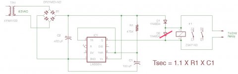
Works fine with the diode as I have it as well. Makes sense since the 555 is the sink in this case. I'm using it as a delay to short out a large resistor until the main caps get charged up a bit. This was from the EZ125 KT88 project I did a while back.
Sandy
Sandy
Attachments
- Status
- This old topic is closed. If you want to reopen this topic, contact a moderator using the "Report Post" button.
- Home
- Amplifiers
- Tubes / Valves
- My KT88 Williamson Amp Build