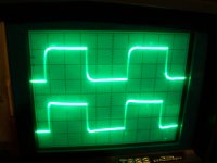
Here are two square wave traces from an output transformer that is 6K6 to 8/16
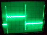
Both are at 10K, the one with the visible ringing is from the 8 Ohm tap unloaded the second is with an 8 ohm resistor across the 8 ohm secondary. I’ve seen the rolled off front edge before but what is the spike at the back side? While I am on the subject, can anyone point me to a good tutorial on interpreting square wave response? Please excuse the picture quality
Thanks,
Marty
Attachments
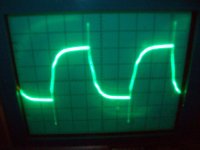
The unloaded tap is the classic under-dampened square wave. It will ring, and is not good for tube outputs.
Loaded waveform shows over-dampened response, loss in high freq band.
Here is an explanation on how to interpret the results.
http://www.kennethkuhn.com/students/ee351/text/square_wave_testing.pdf
Loaded waveform shows over-dampened response, loss in high freq band.
Here is an explanation on how to interpret the results.
http://www.kennethkuhn.com/students/ee351/text/square_wave_testing.pdf
Last edited:
A fundamental square wave test frequency of 10KHz is improper for analyzing output transformers. To reproduce a square wave without distortion, the transformer must be capable of passing frequencies of F/10 and Fx10. This means if a fundamental square wave of 10KHz is applied to a transformer, the transformer must have a bandwidth out to 100KHz. Something virtually no standard power output transformer really has.
Testing with a 2KHz fundamental will equate out to 20KHz. One could even push this fundamental up a little more to perhaps 3KHz, but not 10KHz. For a low end of 30Hz, a fundamental of 300Hz should be used. 20Hz would require 200Hz and so on.
Testing with a 2KHz fundamental will equate out to 20KHz. One could even push this fundamental up a little more to perhaps 3KHz, but not 10KHz. For a low end of 30Hz, a fundamental of 300Hz should be used. 20Hz would require 200Hz and so on.
A fundamental square wave test frequency of 10KHz is improper for analyzing output transformers.
True, to see a perfect 10KHz square wave you need frequency response from 1KHz to 100KHz. But we can look at the "imperfectness" of a 10KHz square wave to judge the RELATIVE merits of a few OPT's under the same conditions, and we can use that 10KHz square wave to tweak the components in the NFB loop for best response. Achieving the best looking square wave for a given OPT's correlates well with good sounding high frequencies. Too much leading edge roundness sounds dull, too much ringing sounds brash and annoying.
The photo shows a 10KHz square wave at 1 watt through a Simple P-P using some OPT's that I paid $16 for. The OPT's were designed for guitar amps and use no interleaving whatsoever. The transformers were made by Schumaker using the same technology applied to their battery chargers.
Spikes like those are an indication of some really high frequency energy. That didn't come through the OPT. I would suspect some interaction between the scope and the circuit. Do you have one end of the secondary grounded? Is this measured in an amplifier? If so, do not run the amp unloaded. As mentioned it can lead to damage in most tube amps.
Attachments
A fundamental square wave test frequency of 10KHz is improper for analyzing output transformers. To reproduce a square wave without distortion, the transformer must be capable of passing frequencies of F/10 and Fx10. This means if a fundamental square wave of 10KHz is applied to a transformer, the transformer must have a bandwidth out to 100KHz. Something virtually no standard power output transformer really has.
Testing with a 2KHz fundamental will equate out to 20KHz. One could even push this fundamental up a little more to perhaps 3KHz, but not 10KHz. For a low end of 30Hz, a fundamental of 300Hz should be used. 20Hz would require 200Hz and so on.
Another way to think of it is in terms of the input square wave's amplitude and the gain and frequency-response of the amplifier, and band-limiting a test-input square wave so that it doesn't try to exceed the maximum slew-rate that can be achieved by all parts of the amplifier (unless, of course, you're hoping to excite any high-frequency instabilities that might be lurking in the amp).
After all, even a low-frequency square wave could have rise and fall times that might try to induce output slew-rates that far exceed an amplifier's capabilities. i.e. The frequency of the square wave, which is just its "repetition rate", is not nearly as important for this purpose as, and is not necessarily even related to, its rise and fall times.
I did a little work on this, when trying to simulate amplifier responses to square wave inputs, with capacitive loads. Here is one of the relevant threads, where I have included the necessary calculations in one of the posts:
http://www.diyaudio.com/forums/solid-state/117469-square-wave-testing-slew-rate.html
Tom
Last edited:
Thanks for all of the replies
Just for clarification, I was testing the transformer itself not a whole amp. There was only 10vrms on the primary from a 600 ohm source. My main goal was to find the turns ratio with a sine wave which was easy enough. I was more or less messing around when I switched to square waves and saw the weird spikes at high frequencies.
Just for clarification, I was testing the transformer itself not a whole amp. There was only 10vrms on the primary from a 600 ohm source. My main goal was to find the turns ratio with a sine wave which was easy enough. I was more or less messing around when I switched to square waves and saw the weird spikes at high frequencies.
I believe that the primary cause is the leakage inductance for this transformer which maybe be a bit high. This means that the coupling in between the windings is not that good or the turns distribution in between layers has not been maximized. To measure the leakage inductance, you will need to short all other windings then with an LCR meter, measure the inductance of the concerned winding.
Last edited:
Where did you find this from ? That's only possible from a theoretically perfect transformer. In the real world equals compromises.. Especially when going from class AB, mismatches,overshoots, misbalanced wiring, Miller effects and so on. Also not forgetting the probe and ground compensation. We have to accept much less.A fundamental square wave test frequency of 10KHz is improper for analyzing output transformers. To reproduce a square wave without distortion, the transformer must be capable of passing frequencies of F/10 and Fx10.
It doesn't correlate with Fourier analysis. With global NFB, the old rule was a transformer reproducing a 10Khz square wave should see
minimal 3rd harmonic attenuation at 30Khz. So a transformer with good response at 20Khz should imply a droop not less than -3dB down at 60Khz.
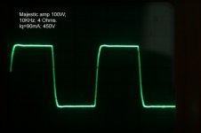
So in p-p tube amps using global nfb, the 5th harmonic is already very low and I ignore this. The result is then an amplifier design based on 3rd harmonic and the enclosed is a 10Khz square wave pic of high power p-p 100W amp at rated o/p. The response of transformer (E&I) was specified by the maker as -3dB at 70Khz which for it's size is a very well designed balanced component and the resonant frequency at approx 100Khz. The final amp response was trimmed at 55Khz by both combination of trimming the Bode plots of the 1st stage and the capacitor on the 20dB global nfb loop.
The result is fully optimised.
Attachments
Thanks for all of the replies
Just for clarification, I was testing the transformer itself not a whole amp. There was only 10vrms on the primary from a 600 ohm source. My main goal was to find the turns ratio with a sine wave which was easy enough. I was more or less messing around when I switched to square waves and saw the weird spikes at high frequencies.
Too low source impedance !
Use stated load at secondary and a source impedance equal to the reflected load at primary.
So, use a 8 ohms load and a 6K resistor in serie with your .6K source.
As already stated, you may observe different results according the end of the primary you will ground.
Yves.
Too low source impedance !
Use stated load at secondary and a source impedance equal to the reflected load at primary.
So, use a 8 ohms load and a 6K resistor in serie with your .6K source.
As already stated, you may observe different results according the end of the primary you will ground.
Yves.
Yes, I think you are right. From the little I know I would expect the low source impedance to cause problems. I don’t know how much I could tell about the transformer testing it at such a low level anyway. I was more curious about the spikes which I had not seen before. I have never tested high level transformers only small signal stuff and I am careful to use driving and loading impedances that match my intended application.
I believe that the primary cause is the leakage inductance for this transformer which maybe be a bit high. This means that the coupling in between the windings is not that good or the turns distribution in between layers has not been maximized. To measure the leakage inductance, you will need to short all other windings then with an LCR meter, measure the inductance of the concerned winding.
I did a little work on getting transformer spice models from simple measurements of real transformers, a while back. I am not really sure how well the leakage inductance is modeled, but at least an LCR meter was not required, which was a good thing for those of us who do not have one. However, I was only working with mains power transformers that had either a single primary and secondary or two indentical primaries and two indentical secondaries. So I don't know how applicable the method might be, for output transformers.
It is based on a paper about transformer modelling that is available from Onsemi:
http://www.onsemi.com/pub/Collateral/AN1679-D.PDF
Here is a link where I have the simplified measurement steps and calculations (and the downloadable LTspice transformer-modelling file) posted:
Spice Component and Circuit Modeling and Simulation
Comments on shortcomings or possible improvements would be welcomed.
Cheers,
Tom
Last edited:
Yes, I think you are right. From the little I know I would expect the low source impedance to cause problems. I don’t know how much I could tell about the transformer testing it at such a low level anyway. I was more curious about the spikes which I had not seen before. I have never tested high level transformers only small signal stuff and I am careful to use driving and loading impedances that match my intended application.
Actually, the spikes would also be there even if you tried a square wave with a plain inductor/coil/choke, instead of with an inductor that's part of a transformer.
For any inductor, V = L (di/dt), where di/dt is just the rate-of-change of the current. The rising and falling edges of the square waves make the current through the inductor change at a very high rate. So L times that high rate gives a large V, during those times, which shows up as voltage spikes.
Tom
can we see what the square wave unloaded looks like?
can we see what the square wave loaded with somethinglike the primary impedance of the xfrmr (an equivalent resistor) looks like?
talking about the generator, not connected to the xfrmr?
fwiw, afaik, driving a higher Z primary with a lower Z source is not an issue, and should not cause the overshoots shown.
_-_-bear
Actually, the spikes would also be there even if you tried a square wave with a plain inductor/coil/choke, instead of with an inductor that's part of a transformer.
For any inductor, V = L (di/dt), where di/dt is just the rate-of-change of the current. The rising and falling edges of the square waves make the current through the inductor change at a very high rate. So L times that high rate gives a large V, during those times, which shows up as voltage spikes.
Tom
Thanks Tom,
Bear,
The square wave from the generator looks fine none of the spikes or ringing.
Well, it's not that it's changing the current fast, in fact if you connect a small resistor in series and measure it, you'll see the magnetizing current is an excellent triangle wave. This is because EMF is constrained by the source: as you say, V = L * dI/dt. The triangle wave is the resulting dI/dt slope. Those spikes are most certainly not the result of rapid current change.
A positive spike on the falling edge is some sort of feedforward or nonminimum phase reaction. I wonder if there is parasitic capacitance coupling the falling edge from the inverting side of the transformer through to the output. It could also be a faithful reproduction of crud on the source, which is a good reason why some have asked for the source waveform.
As for meaning, if you want to get uselessly technical, it's simply the convolution of your input signal with the frequency transfer function of the transformer. On a simpler level, there are L's and C's inside and excitation makes them ring. Underdamped resonances ring like a bell, while overdamped resonances thud more like a lead brick.
Of interest to feedback, you want the closed loop combination of amplifier (with its limited frequency response, at HF and LF, both of which are easy to calculate) and transformer (which has many, many poles and zeros, but can be approximated by a few simple poles) to come out stable (no oscillation, little ringing), and better yet, come out better than stable (i.e., overdamped, no overshoot), so it will also tolerate bad loads.
Tim
Well, it's not that it's changing the current fast, in fact if you connect a small resistor in series and measure it, you'll see the magnetizing current is an excellent triangle wave. This is because EMF is constrained by the source: as you say, V = L * dI/dt. The triangle wave is the resulting dI/dt slope. Those spikes are most certainly not the result of rapid current change.
It depends on the resistance of the source, relative to the inductance: The current is only a triangle wave if the resistance is (relatively) very small. And in that case, the voltage becomes a square wave. For a large-enough resistance, the current becomes a square wave and the voltage is spikes.
A positive spike on the falling edge is some sort of feedforward or nonminimum phase reaction. I wonder if there is parasitic capacitance coupling the falling edge from the inverting side of the transformer through to the output. It could also be a faithful reproduction of crud on the source, which is a good reason why some have asked for the source waveform.
Yeah, I didn't notice that the spikes on the falling trailing edges were the wrong sign for V=L(di/dt) of the primary's inductance. It seems like something more interesting is going on, there.
As for meaning, if you want to get uselessly technical, it's simply the convolution of your input signal with the frequency transfer function of the transformer. On a simpler level, there are L's and C's inside and excitation makes them ring. Underdamped resonances ring like a bell, while overdamped resonances thud more like a lead brick.
Actually, it would be the convolution of the time-domain input signal with the time-domain impulse response of the transformer, not with the frequency-domain transfer function. (I've been out of school for a very long time and had to look it up. But mixing the time and frequency domains just didn't sound right. Plus I remembered the convolution integral mainly being used in the time domain.)
Of interest to feedback, you want the closed loop combination of amplifier (with its limited frequency response, at HF and LF, both of which are easy to calculate) and transformer (which has many, many poles and zeros, but can be approximated by a few simple poles) to come out stable (no oscillation, little ringing), and better yet, come out better than stable (i.e., overdamped, no overshoot), so it will also tolerate bad loads.
Tim
I sort-of specialized in Automatic Control Theory. But that was decades ago and it's all somewhat rusted, and is creaky and half-frozen, now. I remember Critical Damping (damping factor = 0.7); fastest response with no overshoot. But that's just Classical control theory. With Modern or Optimal control theory, or whatever the latest nomenclature is, we'd want the control system to "turn it up to 11" until the last possible instant and then stomp really hard, once, on the perfectly-compensated "brakes", as it were, and be spot on without a quiver (in some n-dimensional space, of course).
- Tom
Last edited:
Some related questions......
I've noticed that in my own testing (and in Tubelab's post #5 above), that the square wave response is not symmetrical.......why is that? The wiggles on the top of the wave are different than the bottom.
What input/output level should one use for square wave testing?
I've noticed that in my own testing (and in Tubelab's post #5 above), that the square wave response is not symmetrical.......why is that? The wiggles on the top of the wave are different than the bottom.
What input/output level should one use for square wave testing?
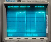
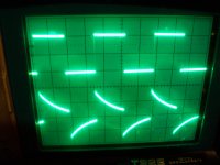
More shots for the curious. This time I added 820 ohm resistors in series with both legs of the primary and an 8 ohm resistor across the secondary. Top trace is the primary and bottom trace is the secondary. The hf shot is at 20K this time and the lf trace is 100 Hz. The phase shift you see in the lf trace was not there when the primary was driven directly from the 600 ohm source.
Attachments
- Status
- This old topic is closed. If you want to reopen this topic, contact a moderator using the "Report Post" button.
- Home
- Amplifiers
- Tubes / Valves
- What gives with this square wave?