Hello to everyone,
After reading some related articles, it is not clear to me how to decide tube operational parameters and draw an optimal load line for a cathode follower buffer.
I have seen many ECC88 CF circuits using different operating points.
Morgan Jones in his book is using anode to cathode voltage = 81V, Ia aprox. 2mA.
Other designs (including the one i currently use) are calculated for anode to cathode voltage = 180V and Ia near 10mA. How can i choose the parameters for best linearity?
My application is a capacitor coupled balanced cathode bias cathode follower buffer using ECC88 tubes which is connected between a balanced TVC and a pair of active monitors with 10K impedance balanced inputs.
Any recommendations would be highly appreciated.
Why dont you search for the "heretical unity gain stage" by SY. There is ecc88 in there and it is a minimal distortion circuit. You shold really just build it as it is just what you need. TVC+heretical beats everything I`ve heard. And you can drop the input transformer too.
The loadline is done exactly the same way as if the load were in the plate circuit. However, the distortion is reduced by a factor of (mu + 1).
Thank you for your reply,
Can i use your design for balanced signal output by using 2 buffers per channel?
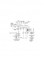
This is the line stage I've used for some 40 yrs that can take parallel balanced lines:The tube CCS has changed to SS.(SY's equivalent circlotron has eliminated the expensive o/p cap by using an IC servo) and I use both parallel sections. A relay is used on warmup to avoid DC cap charge up through the core.
That 1173 parafeed is an exotic Mumetal 3:1 step down. It isn't cheap but the performance is worth it. Those will notice the massive headroom of such a stage and the low o/p Z. The bootstrap input is another bonus and a standard 250K log vol control can be fitted without serious mid travel HF degrading.
It's up to you !
richy
Attachments
Very nice, thank you.
What would be the disadvantage by not using an output transformer and use seperately each ECC88's triode section for (+) and (-) signals and use seperate CSS for each cathode? Of couse i need two input and ouput capacitors, but is there any other problem performance-wise?
What would be the disadvantage by not using an output transformer and use seperately each ECC88's triode section for (+) and (-) signals and use seperate CSS for each cathode? Of couse i need two input and ouput capacitors, but is there any other problem performance-wise?
Why dont you search for the "heretical unity gain stage" by SY. There is ecc88 in there and it is a minimal distortion circuit. You shold really just build it as it is just what you need. TVC+heretical beats everything I`ve heard. And you can drop the input transformer too.
I just had a closer look to your implementation of SY's buffer stage and it seems it's not the version with the DC servo. The board is your build?
Hello to everyone,
After reading some related articles, it is not clear to me how to decide tube operational parameters and draw an optimal load line for a cathode follower buffer.
I have seen many ECC88 CF circuits using different operating points.
Morgan Jones in his book is using anode to cathode voltage = 81V, Ia aprox. 2mA.
Other designs (including the one i currently use) are calculated for anode to cathode voltage = 180V and Ia near 10mA. How can i choose the parameters for best linearity
Don't worry about it. In the first place, the VT doesn't care if the load is connected between the plate and DC rail, or if it's connected between the cathode and DC ground. Either way, it's the same loadline. This is what trips up a good many designers: they figure that just because they have a cathode follower with a Zo= 600R that it can drive a 600R load. It just isn't so.
Secondly, cathode followers are a good deal more "forgiving" than grounded cathode or grounded grid designs. As for how to do the design, see here.
The Red line represents your DC load. Since this follower is connected directly to the grids of the finals, it is also the AC loadline. Once you have that established, it's a simple matter to pick off a Q-Point. Once you know that, then you need the Max and Min plate currents, which will, of course, be equal to the cathode currents. Next:
Vrk(max)= 100 X 4.06= 406V
Vrk(min)= 100 X 1.56= 156V
Since the far end of that cathode load resistor is returned to a -300Vdc rail, figure the actual cathode voltages:
Vk(max)= 406 - 300= +106Vp (Vgk= 0V)
Vk(min)= 156 - 300= -144Vp (Vgk= -15V)
Giving: Vo= 106 - (-144)= 250Vp-p
The input voltages:
Vi(+)= +106V (To make Vgk= 0)
Vi(-)= -144 -15= -159V (To make Vgk= -15V)
Vi= 106 - (-159)= 265Vp-p
Av= 250 / 265= 0.94
Estimate THD in the usual manner:
Iave= (Ip(max) + Ip(min)) / 2
Iave= (4.06 + 1.56) / 2= 2.81mA
Difference from Ipq:
Idiff= 2.81 - 2.75= 0.06
THD= Idiff / Io
0.06 / (4.06 - 1.56)= 0.024 (2.4%)
In cathode follower service, the actual THD estimate will be the grounded cathode estimate times the gain difference: the ratio of the different Vi's.
THD`= 2.4(15 / 265)= 0.14%
Attachments

Thank you for your analysis and calculations.
These are very helpful.
I just cannot understand how do i determine min and max plate currents. The ECC88 datasheet states typical Ia=25mA. Also the follower is not directly connected to a next stage grid, it is just a buffer to drive a pair of active monitors with 10K input impedance.
These are very helpful.
I just cannot understand how do i determine min and max plate currents. The ECC88 datasheet states typical Ia=25mA. Also the follower is not directly connected to a next stage grid, it is just a buffer to drive a pair of active monitors with 10K input impedance.
Thank you for your analysis and calculations.
These are very helpful.
I just cannot understand how do i determine min and max plate currents. The ECC88 datasheet states typical Ia=25mA. Also the follower is not directly connected to a next stage grid, it is just a buffer to drive a pair of active monitors with 10K input impedance.
Actually states Ia=15mA

I just cannot understand how do i determine min and max plate currents.
After choosing the quiescent point (-7.5V in this example), you follow the load line from the quiescent point up to the Vgk=0V line. That is your maximum positive Ia swing since you don't drive the grid positive. Because the drive signal is symmetrical around the quiescent -7.5V, its minimum is at -15V. So you can read the maximum negative Ia swing from the intersection of the load line with the Vgk=-15V curve.
Hi. Thank you for all your contributions.
I am still confused about how to plot the load lines in a white cathode follower headphone amplifier
If I plot a line between maximum B+ (220V) and the idle conditions at the cathode resistor of the bottom tube (V= 2.4V, I= 8.9 mA) I’ve got this:
That gives an intersection at V=107.2V and I=17.5mA
Is it the curve for the tube at the top or at the bottom?
I am still confused about how to plot the load lines in a white cathode follower headphone amplifier
An externally hosted image should be here but it was not working when we last tested it.
If I plot a line between maximum B+ (220V) and the idle conditions at the cathode resistor of the bottom tube (V= 2.4V, I= 8.9 mA) I’ve got this:
An externally hosted image should be here but it was not working when we last tested it.
That gives an intersection at V=107.2V and I=17.5mA
Is it the curve for the tube at the top or at the bottom?
Last edited:
Hi Triodethom.
I have already bought the output electrolytic caps (Jensen Audiograde 500uF/300V)
I am using Sennheiser HD650 (300 Ohm)
I find that if I run more current through the first tube, then the signals at the two output tubes are not balanced. I have found that values playing with Orcad, and the result is a nice symetric figure at the output tubes. Anyway, I will keep mixing values to see if I can find another lucky match running more current at the input tube.
(measuring from grid to cathode at each output tube)
Although I still don't know how this may affect the sound
I have already bought the output electrolytic caps (Jensen Audiograde 500uF/300V)
I am using Sennheiser HD650 (300 Ohm)
I find that if I run more current through the first tube, then the signals at the two output tubes are not balanced. I have found that values playing with Orcad, and the result is a nice symetric figure at the output tubes. Anyway, I will keep mixing values to see if I can find another lucky match running more current at the input tube.
(measuring from grid to cathode at each output tube)
An externally hosted image should be here but it was not working when we last tested it.
Although I still don't know how this may affect the sound
Last edited:
I would use them as power supply caps. If you go to Broskie site Tube CAD Journal you will see that the output cap can be smaller than 47 uf for the output . That is film size it also saves you some subsonic rumble that muddies the deep bass .Hi Triodethom.
I have already bought the output electrolytic caps (Jensen Audiograde 500uF/300V)
I am using Sennheiser HD650 (300 Ohm)
I find that if I run more current through the first tube, then the signals at the two output tubes are not balanced. I have found that values playing with Orcad, and the result is a nice symetric figure at the output tubes. Anyway, I will keep mixing values to see if I can find another lucky match running more current at the input tube.
(measuring from grid to cathode at each output tube)
An externally hosted image should be here but it was not working when we last tested it.
Although I still don't know how this may affect the sound
- Status
- This old topic is closed. If you want to reopen this topic, contact a moderator using the "Report Post" button.
- Home
- Amplifiers
- Tubes / Valves
- How to choose an optimal load line for a cathode follwer buffer?