Hi,
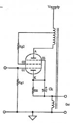
Here are the schematics
It's from VDV, and looks like many AR outputs.
V0 is 720V
V1 is 360V
1 is tied to gnd
OPT is 8K in this configuration.
I have no trouble with the preamp stage, but I'm stuck and lost at the output.
My tube knowledge is far far away and was not so good, I must admit.
Could someone could kindly explain how this thingie work ?
I'm sure I'm stuck by just a little thing my old brain can not understand.
Looks like the cathodes are routed to GND via the 1R and OPT secondary R that is taken at 0 ( ral value seams to be 0R12).
It must be simple and I'm looking for too complicated things, like always
Thanks
Here are the schematics
An externally hosted image should be here but it was not working when we last tested it.
It's from VDV, and looks like many AR outputs.
V0 is 720V
V1 is 360V
1 is tied to gnd
OPT is 8K in this configuration.
I have no trouble with the preamp stage, but I'm stuck and lost at the output.
My tube knowledge is far far away and was not so good, I must admit.
Could someone could kindly explain how this thingie work ?
I'm sure I'm stuck by just a little thing my old brain can not understand.
Looks like the cathodes are routed to GND via the 1R and OPT secondary R that is taken at 0 ( ral value seams to be 0R12).
It must be simple and I'm looking for too complicated things, like always
Thanks
This drawing was not made by Audio Research. Rather, it is a drawing from Manno VanDerVeen's book. Buy it. It has an entire chapter on cathode feedback.
It's not that complicated. The cathodes of the output tube are connected to the OPT secondary, so that both windings of the transformer becomes part of the tube's output circuit. This is "local feedback", which is saying that the OPT primary (at the tube's plate) is providing the driving force, and the OPT secondary (at the tube's cathode) provides negative feedback. It is "local feedback" because the feedback loop only encompasses a single "leg" of the circuit.
Output signal to the loudspeaker is injected to the tube's cathode. This signal modulates the cathode's voltage relative to its grid, therefore imparting negative feedback incorporating the transformer's transfer characteristics and frequency response.
Attachments
As others have stated this amplifier uses Cathode FeedBack. CFB is another method of imposing local negative feedback on a single stage rather than wraping Global Negative FeedBack around the entire amplifier.
Many (including myself) believe that local feedback used to linearize a single stage is far less intrusive than applying GNFB to the entire amplifier chain when only the output stage needs it. I use CFB in the Simple SE amplifier, although it is a user selectable option that some builders do not use.
CFB places the OPT inside the feedback loop, as does GNFB. CFB on a single ended amplifier can work wonders on a marginal OPT. It also reduces the output impedance.
The type of CFB used on this push pull amplifier requires a well balanced OPT. If the two sides of the OPT are not wound in an identical manner the feedback applied to one tube will not be identical to the feedback applied to the other tube. This can force an unbalance over some or all of the audio frequency range, resulting in increased distortion. Many cheap P-P OPT's are wound such that the two primary halves have significantly different winding capacitance and inductance. The same may also be true of the secondary. Using this type of feedback on a push pull OPT that was not designed for it may either increase the distortion or change the distortion signature in an unpleasing way. Audio Research did use this technique, and even stated somewhere that it would not work on OPT's other than their own.
I have had some success implementing it on toroidal OPT's (which VDV advocates), including some cheap power toroids. I have also successfuly used it on a Plitron output toroid that was not designed for CFB, or even HiFi applications. I have tried this connection on some of my cheap guitar amp OPT's that work rather well otherwise and it always winds up casuing an unwanted increase in higher order harmonics.
It must be noted that the 4 ohm tap is electrically the center tap in a 1-4-8-16 ohm OPT. The impedance is the square of the turns ratio.
I used this technique nearly 20yrs ago with amplifiers I designed around Harman-Kardon Citation II output transformers where it worked extraordinarily well in UL connection no less. I found in this case that attenuating the feedback signal by about 6dB prior to application to the cathodes was ideal. There are a number of these amplifiers still lurking around the Boston area. (This works well with some of the smaller Apogees and Maggies which is what they were built to drive.)
Thanks all for your answers
Kashemire: I know the drawing is from VDV, but AR uses this on many tube amps.
Got to buy the book anyway.
Tubelab: thanks fro the precisions.
I think I got the thing now, I slept on it and this morning that was clearer!
I might try this amp if I can get the OPTs at a reasonnable price here or I'll wait for next time I go see my parents in France and I'll get them in my luggages.
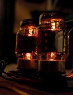
Here's a snapshot of some KT88s in push-pull CFB using Plitron "specialist range" transformers. They are being driven with an LL1660S interstage transformer.
A future project is to finish my "dream amplifier" using these components. Right now, the majority of the work is packaging (chassis) and layout. I have all the parts - power transformer, capacitors, chokes, tubes, sockets, interstage transformer, and output transformer. I'll probably drive the interstage transformer with a Broskie Akikdo linestage.
FYI, here's another great article on CFB, courtesy of the Lundahl folks. Attached schematic of EL34 in CFB single-ended configuration.
Attachments
Last edited:
Kashmire, I use a very similar circuit in the Simple SE. The DC current drawn by the tube through the secondary of the OPT will drop a small voltage across the secondary due to its DC resistance. There are a few people who claim that this small DC voltage can cause a problem with some high efficiency speakers. I don't notice any problem, but my speakers are not high efficiency.
There is however a simple solution. Connect the cathode resistor to ground, but leave the bypass capacitor connected to the OPT secondary. This gets the DC out of the OPT secondary, but now the cathode resistor is effectively in parallel with the output. This will lower the output power by a few milliwatts.
There is however a simple solution. Connect the cathode resistor to ground, but leave the bypass capacitor connected to the OPT secondary. This gets the DC out of the OPT secondary, but now the cathode resistor is effectively in parallel with the output. This will lower the output power by a few milliwatts.
Connect the cathode resistor to ground, but leave the bypass capacitor connected to the OPT secondary.
Oh! That's really nice! Separate DC and AC pathways. That's an elegant solution. May be possible using push-pull also, if you have a reason to eliminate the bias currents from the secondary (although I can't think of a good reason).
Your comment reminds me of a quote:
Make everything as simple as possible, but not simpler.
-Albert Einstein.
Cede: Plitron manufactured in Canada, your neighbor in Ontario. VDV from Europe.
Last edited:
Also got to integrate the WAF factor in the equation!
Eh, right-o.
Right now, the majority of the work is packaging (chassis) and layout.
IMHO, that's the hardest part of the entire project.
I know about Plitron but I find their prices way up but I don't know the quality.
Fwiw a friend with a decent Tango/Tamura/Bartolucci collection really dislikes his Plitrons soundwise.
Analog: looks like the prices are high too !
Can't afford a 800$ OPT, or my wife's and my bank will kill me !
I think I should ask the guy where I leaved in France to make an OPT to match what I need at a decent price. He knows his stuff and many people I talked to using his OPT where pretty satisfied.
Got to grab the other parts while I'll look for the tranny.
- Status
- This old topic is closed. If you want to reopen this topic, contact a moderator using the "Report Post" button.
- Home
- Amplifiers
- Tubes / Valves
- Need help on understanding AudioResearch like output stage