Very basic question...
I just got a tube linestage kit (Bottlehead Foreplay), and would like to modify it to have a home theater bypass: i.e. flip a switch on the chassis and completely bypass the linestage circuits.
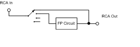
Would something as simple as the attached work?
Any help would be tremendously appreciated!
I just got a tube linestage kit (Bottlehead Foreplay), and would like to modify it to have a home theater bypass: i.e. flip a switch on the chassis and completely bypass the linestage circuits.
Would something as simple as the attached work?
Any help would be tremendously appreciated!
Attachments
Just make sure the switch costs at least as much as the preamp, and has rhodium-plated contacts as a bare minimum!! Don't forget to have it made from hepta-laminated (lucky 7's) silver, copper and gold of only the purest (5-nines minimum (99.999% pure)), most oxygen-free metal possible, and DON'T USE LEADED SOLDER TO MAKE THE CONNECTIONS, use the same grade silver as above, cast in place, to attach to the superconductor wires (what, don't tell me you don't have a supply of liquid nitrogen around!).
Tim
Tim
(sorry if this appears twice - my prior attempt to post it didn't work because the file was too large)
Brett: Thanks for the suggestion! You're totally right, I should put the switch at the output.
If the FP is accidently turned on with the bypass engaged, is that dangerous? Is it bad to have an open circuit at the output?
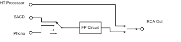
Unless you see anything wronge I'll use the attached, with a dpdt on-none-on before the rca out.
Brett: Thanks for the suggestion! You're totally right, I should put the switch at the output.
If the FP is accidently turned on with the bypass engaged, is that dangerous? Is it bad to have an open circuit at the output?
Unless you see anything wronge I'll use the attached, with a dpdt on-none-on before the rca out.
Attachments
A LITTLE FOREPLAY NEVER HURT ANYONE...
Hi,
No...but: make sure there's a bleeder resistor behind the last coupling cap so no D.C. voltage can develop at the output.
In which case you can even have the FP on in case you want it to warm up for later use while you're watching a DVD or whatever.
Cheers,")
Hi,
If the FP is accidently turned on with the bypass engaged, is that dangerous? Is it bad to have an open circuit at the output?
No...but: make sure there's a bleeder resistor behind the last coupling cap so no D.C. voltage can develop at the output.
In which case you can even have the FP on in case you want it to warm up for later use while you're watching a DVD or whatever.
Cheers,
If I remember right, the FP circuit has a 470K resistor to ground after the coupling cap.
I'm not sure how the first schematic would work. If he switches at the input, then won't he end up with the amp's input impedance and the FP's output impedance in parallel? So his HT source will be driving a much lower impedance. Or is that not how it would work?
I'm not sure how the first schematic would work. If he switches at the input, then won't he end up with the amp's input impedance and the FP's output impedance in parallel? So his HT source will be driving a much lower impedance. Or is that not how it would work?
The other option is to use one of the inputs and add padding resistors to it so you end up with unity gain, or close to it. That way the FP will still be in the circuit, but it won't affect the volume of the front L and R channels (or at least, not too much). Of course, if you don't want the FP's sound in the picture, then you do need a bypass, that depends upon how picky you are about your HT sound.
Edit: I don't know if padding resistors would work, but I'm sure there are ways to make one of the inputs be "unity gain".
Edit: I don't know if padding resistors would work, but I'm sure there are ways to make one of the inputs be "unity gain".
- Status
- This old topic is closed. If you want to reopen this topic, contact a moderator using the "Report Post" button.
- Home
- Amplifiers
- Tubes / Valves
- How to add an HT bypass?