Hi,
A quick question..
I received a reply with an explanation of a test set-up for an OTP I am speculating on for my up coming KT88 PP as I asked for a 10 kHz square wave test results.
They used 2 x 2,5 kOhm, one resistor on each primary tap to which a generator was connected with 2 V peak-peak, and an 8 Ohm resistor on the secondary 8 Ohm output, further on the B+ was connected to the secondary ground, is this correct way to set up an OPT for a square wave behaviour test?
btw this transformer has a 5 kOhm input impedance.
Cheers Michael
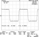
I would like to add also another reason for my question in the first post is because the square wave output looked too good and I have a feeling the 5 k resistors on the primary smooths out and shapes the square wave and dampens out the ringing, is that correct?
Cheers Michael
Cheers Michael
Attachments
I see no problems with the 5k resistors but don't like the ridiculously low voltage/power levels.
Hi,
Thanks for replying, could you please be kind and tell what is the problem with using "ridiculously low voltage/power level"?
Cheers Michael
ok I see, I think I would not be afraid of saturation or how non-linear at first though they are important too, what I want to know foremost right now is if the resonances are affected with the series resistor on the input because the square wave in the picture I provided has almost no ringing.
See here for an example of the measurements of 31 OPT at the Triode Festival autumn 2009 in France: http://forums.melaudia.net/attachment.php?aid=1228
Not all OPT's have an oscilloscope picture but as one can see there are many singing OPT's, but OTOH their measurement setup is different.
And here's the link to the shoot-out info page.
European Triode Festival - ETF2009 Shootout
Unfortunately I don't have the transformer so I can't make any measurements myself.
Cheers Michael
Last edited:
You want to drive the transformer from the same impedance as it will see in "real" use, and terminate it with the same impedance as it will have in "real" use. That's critical for measurement of bandwidth, resonance, and distortion. Unfortunately, it's not a trivial test to do unless you're willing to rig up a generator capable of delivering a few watts at a 100kHz+ bandwidth.
- Status
- This old topic is closed. If you want to reopen this topic, contact a moderator using the "Report Post" button.
- Home
- Amplifiers
- Tubes / Valves
- How to run a square wave test on an OPT??