This is the schematic.
This is the board.
Some wiring information.
The board with parts.
The complete construction.
Inside...
Get the story in pdf.
RapidShare: 1-CLICK Web hosting - Easy Filehosting
or ask for to sent it directly
Get the PCB
PCB FOR TUBE AMPLIFIER EL34 6L6 SINGLE ENDED (PAIR) - eBay (item 320467295208 end time Jan-25-10 10:20:02 PST)
Thanx for passing by!")
An externally hosted image should be here but it was not working when we last tested it.
This is the board.
An externally hosted image should be here but it was not working when we last tested it.
Some wiring information.
An externally hosted image should be here but it was not working when we last tested it.
An externally hosted image should be here but it was not working when we last tested it.
The board with parts.
An externally hosted image should be here but it was not working when we last tested it.
The complete construction.
An externally hosted image should be here but it was not working when we last tested it.
Inside...
An externally hosted image should be here but it was not working when we last tested it.
Get the story in pdf.
RapidShare: 1-CLICK Web hosting - Easy Filehosting
or ask for to sent it directly
Get the PCB
PCB FOR TUBE AMPLIFIER EL34 6L6 SINGLE ENDED (PAIR) - eBay (item 320467295208 end time Jan-25-10 10:20:02 PST)
Thanx for passing by!
I wouldn't have put power lines so close to the board and (especially) the input signal wires.Inside...
An externally hosted image should be here but it was not working when we last tested it.
Evenharmonics, thank you for your comment.
Mains input at the back and power switch in front is taken for granted for me.
In distant future power on switch will drive a relay with a soft start circuit.
It is "distant" because nothing really happens as long the mains wire are twisted and close to chassis.
Mains input at the back and power switch in front is taken for granted for me.
In distant future power on switch will drive a relay with a soft start circuit.
It is "distant" because nothing really happens as long the mains wire are twisted and close to chassis.
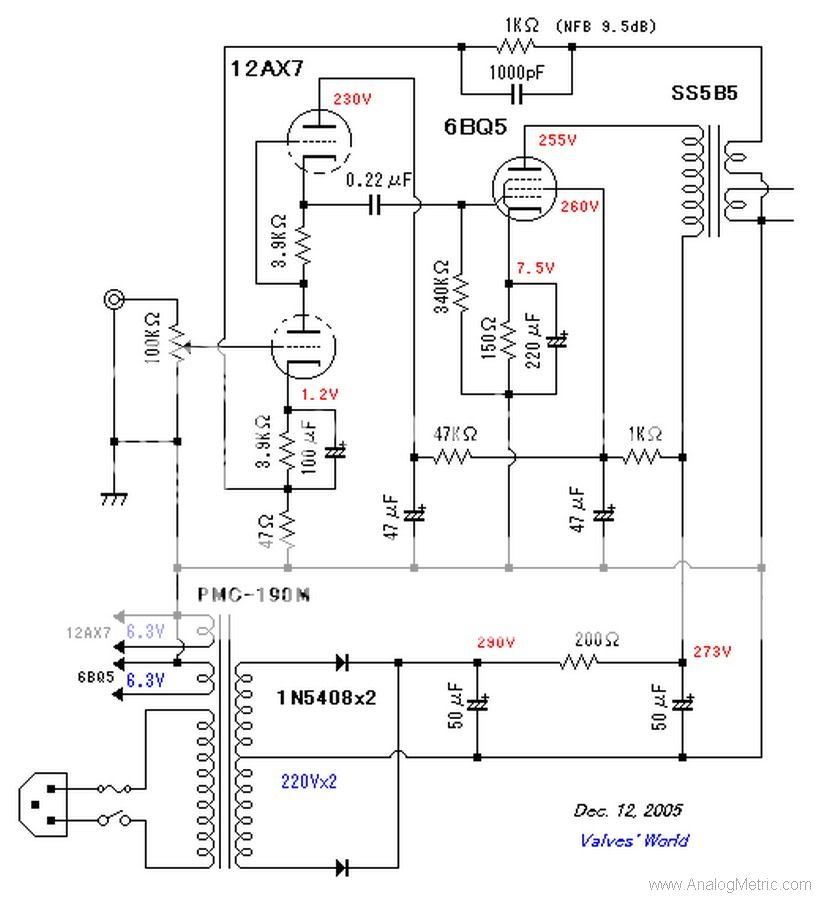
This is the schematic.
Just a tip: Eagle's library "supply" (and numbers after "supply") contains supply symbols which allow you to make your schematics less cluttered (it can be broken into smaller subunits rather than ending up with just one gigantic schematic). All copies of same supply symbol are connected to same signal, so you can use them anywhere you need to connect something to a supply rail (GND, V+, etc.).
Just a tip: .
Thanks Arnulf.
This is the updated pdf with my amplifier's part list.
RapidShare: 1-CLICK Web hosting - Easy Filehosting
Never understood how a push pull input stage could be called SE
Never understood how a se output stage could be called push pull
I think you might be able to get better performance in terms of stability at sub-sonic frequencies by swapping R104 and the R105||C101||C102 combo.
In the current implementation, the global feedback is roughly R104/(R104+R106) at DC. If you swap the two impedances, you'll get (R104+R105)/(R104+R105+R106) at DC. Above the lower -3dB frequency, the feedback factor will be the same for the two implementations as C101||C102 "short out" R105 (i.e. Z = R105||1/wC101||1/wC102 approaches 1/wC101||1/wC102 for high values of w -- w = 2*pi*frequency).
~Tom
I never understood why such a low gm tube like the 12AX7 would be used to drive an output tube, even if it is SRPP. I know there are famous designs that use the 6SL7 in SRPP to drive a 2A3 or 300B. I found that removing the 6SL7 SRPP and replacing it with a normal 6J5 plate follower made a huge difference in dynamics, frequency response, and transparency. I am no fan of SRPP. YMMV...
normal 6J5 plate follower
Not sure what you mean. I find plate followers rarely used. Do you mean you are driving the 300B with a common cathode 6J5? Or that you have a 6J5 plate follower after a 6SL7 common cathode?
I think you might be able to get better performance in terms of stability at sub-sonic frequencies by swapping R104 and the R105||C101||C102 combo.
In the current implementation, the global feedback is roughly R104/(R104+R106) at DC. If you swap the two impedances, you'll get (R104+R105)/(R104+R105+R106) at DC. Above the lower -3dB frequency, the feedback factor will be the same for the two implementations as C101||C102 "short out" R105 (i.e. Z = R105||1/wC101||1/wC102 approaches 1/wC101||1/wC102 for high values of w -- w = 2*pi*frequency).
~Tom
I think you are suggesting the following modification.
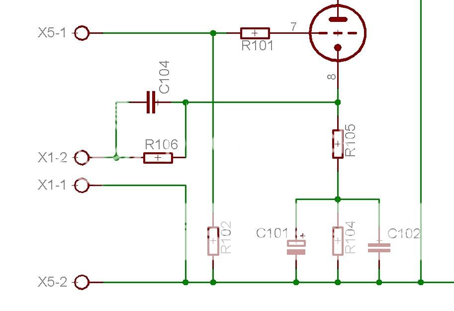
It was one of my first designs. I reject it because the current implementation was so widely used and many have already build it. Thank you for inspecting "my" design!
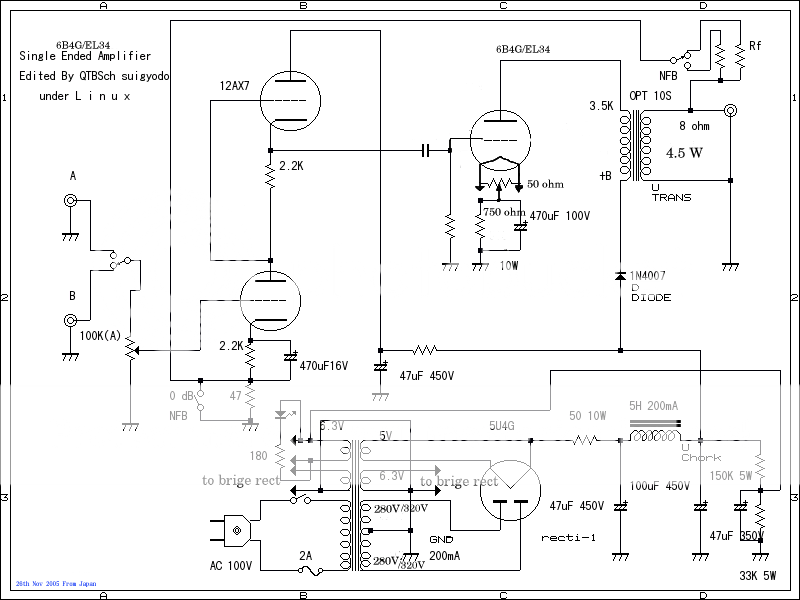
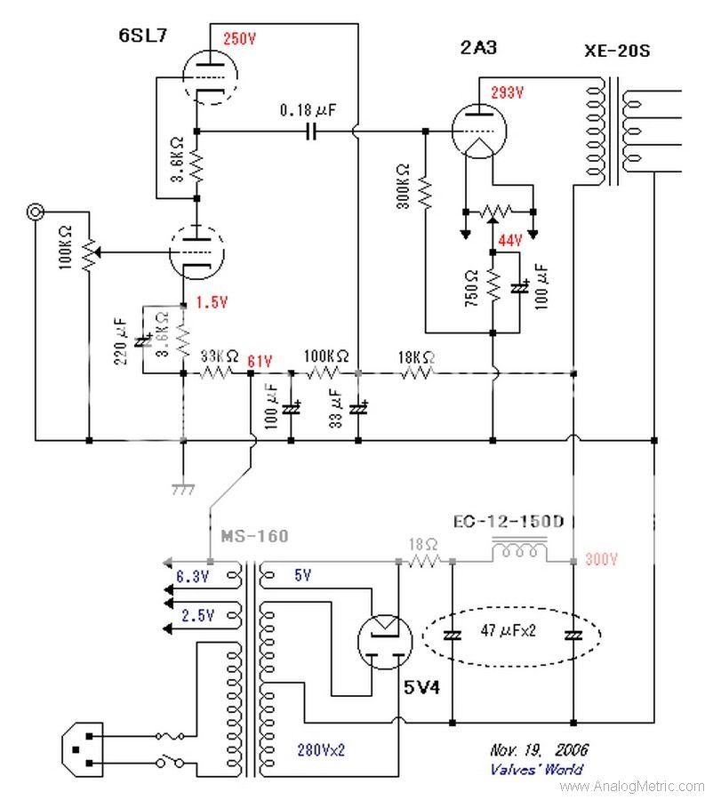
I never understood why such a low gm tube like the 12AX7 would be used to drive an output tube, even if it is SRPP. I know there are famous designs that use the 6SL7 in SRPP to drive a 2A3 or 300B. I found that removing the 6SL7 SRPP and replacing it with a normal 6J5 plate follower made a huge difference in dynamics, frequency response, and transparency. I am no fan of SRPP. YMMV...
So far, i have tested the following driver tubes:
12AX7 Philips ECG (the best)
6189W Sylvania
6922 Sylvania
12AU7A National
12AT7WC GE (the worst)
B+=360V R103=R105=470~2,2K
Surprisingly, the lowest gm tube was the winner. I think the brand name is important too.
Triode driving a triode? I just can't stand so much color in my music.
Never understood how a push pull input stage could be called SE
The SRPP really is both. Try thinking of it as an active pull-up/active pull-down circuit, and it becomes clearer. The upper tube pulls the load up, and the lower tube pulls it down. Even though the load is connected in a single-ended manner, it's still seeing current moving in two directions, so the SRPP really is push pull. This is also why the thing is balanced under just three conditions: dead short on the output (both tubes operating as grounded cathode amps) into an open line (or at least a Hi-Z load) the only current path is through both tubes in series, and at the load impedance for which it was designed, where the source current equals the sink current.
Otherwise, it goes out of balance, and distortion rises with the impedance mismatch.
- Status
- This old topic is closed. If you want to reopen this topic, contact a moderator using the "Report Post" button.
- Home
- Amplifiers
- Tubes / Valves
- A Single Ended presentation